background image

Circuit breakers Emax E1.2-E2.2-E4.2-E6.2 ................................ 3

1 - Contents .........................................................................3

Organization of this handbook .............................................. 3
Intended readership .............................................................. 3
Instructions ........................................................................... 3
Integrated informations ......................................................... 3

Introduction to Ekip trip units ...................................................... 4

1 - Presentation ....................................................................4

Families and functionality ..................................................... 4
Accessorizing modules ......................................................... 5

Ekip Touch protection trip unit .................................................... 6

1 - Layout of the interface ....................................................6

Components of the interface................................................. 6
Signallings ............................................................................ 7
Structure of the pages .......................................................... 7
Diagnosis bar ........................................................................ 7
Main page ............................................................................. 8
Start page ............................................................................. 8

2 - Pages details ..................................................................9
3 - Insertion of the password................................................9

Description ........................................................................... 9
Components of the page ...................................................... 9

4 - Setting the parameters..................................................10

Modifying a parameter ........................................................ 10
Programming the trip unit ................................................... 10

5 - Protections ...................................................................11

Operating principle ............................................................. 11

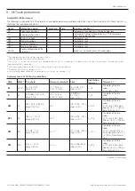
6 - Touch protections .........................................................12

Availability (Performance) .................................................... 12
Neutral ................................................................................ 12
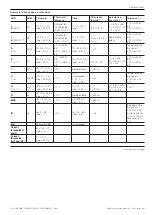
Summary table of basic protections.................................... 13

7 - Measuring Pro protections ............................................15

Availability (Performance) .................................................... 15
Summary table of Measuring Pro protections ..................... 15
Availability (Performance) .................................................... 16
Summary table of Hi-Touch protections .............................. 16

8 - Hi-Touch protections .....................................................16

Availability (Performance) .................................................... 18
Summary table for G Touch protections .............................. 18

9 - G Touch protections ......................................................18

Availability (Performance) .................................................... 20
Summary table of G Hi-Touch protections .......................... 20

10 - G Hi-Touch protections ...............................................20
11 - External toroid protections ..........................................21
12 - Touch measurements ..................................................21
13 - Ekip Measuring Measurements ...................................21
14 - Hi-Touch measurements .............................................21
15 - Test .............................................................................21
16 - Self-diagnosis .............................................................22

Alarms and signals .............................................................. 22
Self-diagnosis ..................................................................... 22
Protections and Measurements .......................................... 23
Programming errors ............................................................ 24

17 - Operating features ......................................................25

Electrical characteristics ..................................................... 25
Functional characteristics ................................................... 26
Additional options via remote / front control ....................... 26

18 - Default parameters......................................................26
19 - Ekip Power Controller .................................................26

Accessories ................................................................................ 27

1 - Preliminary considerations ............................................27

Introduction ........................................................................ 27
Accessory combination tables ............................................ 27
Disassembly operations for circuit breakers E1.2................ 29
Disassembly operations for circuit breakers E2.2-E4.2-E6.2 30

2 - Wiring diagrams ............................................................31

Electronic accessories ............................................................... 31

1 - Introduction ..................................................................31
2 - Ekip Measuring modules ...............................................31
3 - Ekip Synchrocheck module ...........................................31
4 - Ekip Signalling 4K module ............................................31
5 - Ekip Signalling 2K modules ...........................................31
6 - Ekip Signalling 3T modules ...........................................31
7 - Ekip Com Modbus RTU modules ..................................31
8 - Ekip Com Profibus DP modules ....................................31
9 - Ekip Com DeviceNet modules™ ...................................31
10 - Ekip Com Modbus TCP modules ................................31
11 - Ekip Com Profinet modules .........................................32
12 - Ekip Com EtherNet/IP™ modules ...............................32
13 - Ekip Com IEC 61850 modules .....................................32
14 - Ekip Link module ........................................................32
15 - Ekip Com Hub modules ..............................................32
16 - Ekip Com Actuator module .........................................32
17 - Other accessories .......................................................32

© 2018 ABB SACE Emax 2  |  I   

1SDH001316R0002 - ECN000086018 - Rev. C

Содержание SACE Emax 2

Страница 1: ...DOC N 1SDH001316R0002 ECN000086018 Rev C SACE Emax 2 Low voltage air circuit breakers Emax E1 2 E2 2 E4 2 E6 2 Instructions for using Ekip Touch protection trip units and Accessories...

Страница 2: ...ABB SACE Emax 2 2 2018 ABB 1SDH001316R0002 ECN000086018 Rev C...

Страница 3: ...tions 20 10 G Hi Touch protections 20 11 External toroid protections 21 12 Touch measurements 21 13 Ekip Measuring Measurements 21 14 Hi Touch measurements 21 15 Test 21 16 Self diagnosis 22 Alarms an...

Страница 4: ...II 2018 ABB SACE Emax 2 1SDH001316R0002 ECN000086018 Rev C...

Страница 5: ...field IEV 195 04 02 person adequately advised or supervised by electrically skilled persons to enable him or her to perceive risks and to avoid danger which electricity can create NOTE This manual spe...

Страница 6: ...LI LSI LSIG Ekip Touch LI LSI LSIG Ekip Hi Touch LSI LSIG Ekip G Touch LSIG Ekip G Hi Touch LSIG The Ekip Touch trip unit can be equipped with the Ekip Measuring module to extend the measurement funct...

Страница 7: ...DP Ekip Com DeviceNet Ekip Com Modbus TCP Ekip Com Profinet Ekip Com EtherNet IP Ekip Com IEC 61850 Ekip Com Hub Communication module Link Communication module The modules external to the circuit brea...

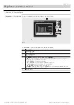
Страница 8: ...A Touchscreen display B Power LED green C LED Warning yellow D LED Alarm red E The HOME key accesses the main page or the initial page F iTEST key If the main page or a level 2 page is displayed see b...

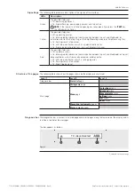
Страница 9: ...rization error On fixed prealarm of protection L or circuit breaker state error Red The possible states are Off no alarm or error On blinking rapidly absence of communication between trip unit and Mai...

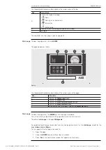
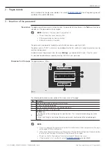
Страница 10: ...es a description of the various areas of the page Pos Function A It opens the Histograms page B It opens the Menu page C It opens the Measuring instruments page D It opens the Measurements page E In t...

Страница 11: ...m New Password It is possible to disable the password by inserting 00000 as new password Components of the page The page appears as follow C D 0 A B E Password Confirm Figure 5 The following table pro...

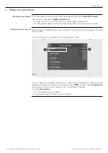
Страница 12: ...t When a parameter is modified the new value is indicated in the Start menu and the parameter is associated to a tick symbol The menu with submenus and parameters with ticks appears as follows S V Pro...

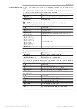
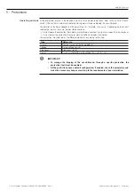
Страница 13: ...above the protection threshold persistent alarm condition the trip unit will open the circuit breaker Current below the protection threshold alarm condition and delay interrupted The protection thresh...

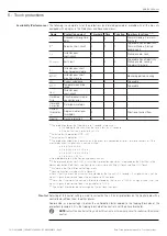
Страница 14: ...le with protection MCR Off 3 Activatable with protection I Off 4 The protection automatically deactivates in the event of a connection error of 1 or more sensors or if the measured current is higher t...

Страница 15: ...er of the two values 10 or 40 ms S t k I 2 51 I2 0 6 10 In step 0 1 In 7 with If 6 In 10 with If 6 In t2 0 05 0 8 s step 0 01 s t t 100 t2 If 2 t t 5 s con I2 1 In t2 0 8 s If 4 In 15 with If 6 In 20...

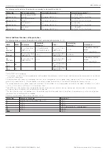
Страница 16: ...1 s t t t4 The better of the two values 10 or 40 ms S SdZ 68 t2 SdZ 0 04 0 2 s step 0 01 s G SdZ 68 t4 SdZ 0 04 0 2 s step 0 01 s 1 ANSI IEEE C37 2 encoding 2 t t calculation is valid for If values ex...

Страница 17: ...1 5 Un step 0 001 Un 2 t9 0 05 120 s step 0 01 s t t t9 The better of the two values 10 or 40 ms for a time set 5 s 100 ms for a time set 5 s VU 47 U14 2 90 step 1 5 t14 0 5 60 s step 0 5 s t t t14 T...

Страница 18: ...error and forces the parameter to 0 4 seconds 4 Directional Zone Selectivity works as an alternative to S and G Zone Selectivity 5 Protection not active for voltages 30V 6 The protection does not dete...

Страница 19: ...30 s step 0 01 s t t t7 startup The better of the two values 10 or 40 ms D SdZ 68 t7 SdZ 0 1 0 8 s step 0 01 s 1 Calculation of t t is valid for values exceeding the tripping threshold of the protect...

Страница 20: ...reshold Tolerance threshold Tripping time Calculation formula t t 1 Tolerance t t 2 S V Step 51V I20 0 6 10 In step 0 1 In 6 Ul 0 2 1 Un step 0 01 Un Ks 0 1 1 step 0 01 6 10 t20 0 05 30 s step 0 01 s...

Страница 21: ...se conditions are not guaranteed the tripping time tolerance of 10 will become 20 3 The tripping threshold of the current for voltage values between Ul and Uh is calculated by performing the linear in...

Страница 22: ...5 1 0 1 Sn step 0 001 Sn Kq 2 2 step 0 01 Kq2 2 2 step 0 01 Vmin 0 5 1 2 Un step 0 01 10 t24 0 5 100s step 0 1 s t t t24 The better of the two values 10 or 40 ms for a time set 5 s 100 ms for a time s...

Страница 23: ...manual 1SDH001330R0002 Emax 2 engineering manual available on the website ABB library 13 Ekip Measuring Measurements Details related to this chapter are available in the manual 1SDH001330R0002 Emax 2...

Страница 24: ...I4 becomes 1200 A in the case of UL circuit breaker Internal Error Internal error Invalid Date Date not set CB status CB state incorrect esample current present but CB in open state Rating Plug Instal...

Страница 25: ...s 1SDH000999R0002 for Emax E1 2 and 1SDH001000R0002 for Emax E2 2 E4 2 and E6 2 Protections and Measurements In the event of protection or measurement alarms the associated signals are reported Signal...

Страница 26: ...vation of Zone Selectivity with protections S S2 G or Rc enabled S V t20 and S V I20 error Incorrect configuration of S V protection RQ Q24 Q25 Incorrect configuration of RQ protection SYNCHRO paramet...

Страница 27: ...e 80 V Auxiliary power supply All the trip units of the Ekip Touch range can be connected to an external auxiliary power supply source useful to activate certain functions such as communication on a L...

Страница 28: ...remote front control Ekip T P Ekip Programming and Ekip Bluetooth allow the protection trip unit to be connected to Ekip Connect software and to access parameters and commands that cannot be accessed...

Страница 29: ...R R Electrical control YO 4 YC R R YO2 4 R R YU 2 4 R R M R R YR R Security mechanical KLC PLC R R KLP PLP 1 R R SL 1 S S DLC R R Anti insertion lock S S MOC R R FAIL SAFE 3 R R Protection mechanical...

Страница 30: ...teral fastening 6 Incompatible with YR The following table shows the possible combinations of the electronic accessories Type of accessory Accessory Trip units Ekip Dip Ekip Touch Ekip Hi Touch Ekip G...

Страница 31: ...s the lateral protection D by fixing the screws C and E A D C E B F Figure 7 Removing the front cover and protections After reassembling the accessories the parts previously dismantled must be reassem...

Страница 32: ...B C 2 1 90 1 2 Figure 9 Removing the flange and front cover After reassembling the accessories the parts previously dismantled must be reassembled as indicated Front cover of the circuit breaker C by...

Страница 33: ...ax 2 engineering manual available on the website ABB library 5 Ekip Signalling 2K modules Details related to this chapter are available in the manual 1SDH001330R0002 Emax 2 engineering manual availabl...

Страница 34: ...manual 1SDH001330R0002 Emax 2 engineering manual available on the website ABB library 14 Ekip Link module Details related to this chapter are available in the manual 1SDH001330R0002 Emax 2 engineerin...

Страница 35: ...ABB SACE Emax 2 Electronic accessories 11 Ekip Com Profinet modules 33 2018 ABB 1SDH001316R0002 ECN000086018 Rev C...

Страница 36: ...1SDH001316R0002 ECN000086018 Rev C...

Отзывы: