


Installation
16
RHD250 ... 4000 42/68-165-EN
Pos: 8.22 /Montage/Aktorik/Elektr. Schwenkantriebe/RHD250...4000/Montage mit Hebeltrieb @ 14\mod_1194260399171_3101.doc @ 135753
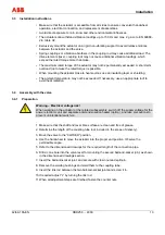
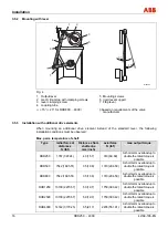
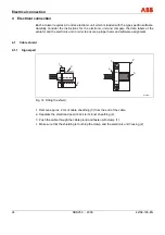
3.5.2 Mounting
with
lever
b
a
1
2
3
5
4
6
7
3°
10°
M00303
Fig. 4
1
Output lever
2
mech. limit stop with clamping screws
3
lever clamping screw
4
coupling tube
α
≥
15° (
≥
20° for RHD800 ... 4000)
5
Mounting screws
6
rigid, level support
7
Flap lever
β
based on requirements of the valve
manufacturer
Pos: 8.23 /Montage/Aktorik/Elektr. Schwenkantriebe/RHD250...4000/Montage mit anderen Abtriebselementen @ 14\mod_1194272226406_3101.doc @ 136108
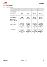
3.5.3 Installation with additional drive elements
When mounting an additional drive element instead of the standard lever, the following
installation conditions must be observed:
Max. perm. temperature of shaft:
Type
radial force at
distance x
N (lbf)
Distance x from
shaft edge
mm (inch)
axial force
N (lbf)
max. output torque
RHD250 1767
(397.24)
40 (1.57)
310 (69.69)
A short-term overload up to
double the rated torque is
possible
RHD500 7542
(1695.51) 35
(1.38) 1310 (294.50)
A short-term overload up to
double the rated torque is
possible
RHD800 7542
(1695.51) 35
(1.38) 1310 (294.50)
A short-term overload up to
double the rated torque is
possible
RHD1250 10100
(2270.57)
50
(1.97) 1750 (393.42)
A short-term overload up to
double the rated torque is
possible
RHD2500 10100
(2270.57)
50
(1.97) 1750 (393.42)
A short-term overload up to
double the rated torque is
possible
RHD4000 14142
(3179.25)
55
(2.17) 2455 (551.91)
A short-term overload up to
double the rated torque is
possible
Pos: 8.24 /Montage/Aktorik/Elektr. Schwenkantriebe/RHD250...4000/Gestaltung der Antriebselementnabe @ 14\mod_1194420363093_3101.doc @ 136723


