


Installation
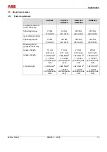
42/68-165-EN RHD250 ... 4000
13
Pos: 8.8 /Überschriften/1.1/1-spaltig/M - O/Montagehinweise @ 10\mod_1181632708234_3101.doc @ 103461
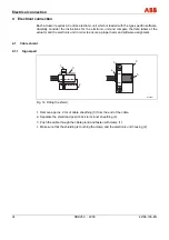
3.3
Installation instructions
Pos: 8.9 /Montage/Aktorik/Elektr. Schwenkantriebe/RHD250...4000/Montagehinweise @ 16\mod_1197272970281_3101.doc @ 145009
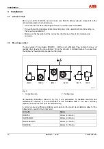
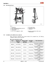
• Make sure that the actuator is accessible from all sides to ensure convenient handwheel
operation, electrical connection, and replacement of assemblies.
• Avoid direct exposure to rain, snow and other environmental influences.
• The actuators can withstand vibration loadings up to 150 Hz and max. 2 g acc. to EN 60068-
2-6, table C2.
• Exclusively mount the actuator on a rigid, non-vibrating support to avoid relative motions
between the actuator and the valve.
• Spring couplings or vibration absorbers in the coupling rod may cause additional load. The
drive elements (lever, coupling rod) may not cause additional vibration loadings, which
exceed the rated torque more than twice.
• The maximum rated torque of the actuator may not be permanently exceeded. A short-term
overload (up to twice the rated torque) is possible.
• When mounting the actuator close to heat sources use an insulating layer or shielding.
• The ambient temperature may not be exceeded. If necessary, use an appropriate roof to
avoid heat radiation.
Pos: 8.10 /Überschriften/1.1/1-spaltig/V - Z/Zusammenbau mit dem Stellglied @ 10\mod_1181634985953_3101.doc @ 103507
3.4
Assembly with the valve
Pos: 8.11 /Überschriften/1.1.1/1-spaltig/Vorbereitung @ 10\mod_1181635035296_3101.doc @ 103530
3.4.1 Preparation
Pos: 8.12 /Montage/Aktorik/Elektr. Schwenkantriebe/Allgemein/Vorbereitung @ 10\mod_1181569909062_3101.doc @ 103083
Warning – Electrical voltage risk!
When working on the actuator or the related subassembly, switch off the supply voltage for the
power electronic unit and separate anti-condensation heater (option), and take precautions to
prevent unintentional switch-on.
1.
Make sure that the shaft and lever bore surface are clean and free of grease.
2.
Determine the length of the coupling tube (not included in the scope of delivery).
3.
Move the valve to the "CLOSED" position.
4.
Use the handwheel to move the actuator into the proper end position. Observe the
permissible angle.
5.
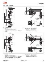
Refer to the dimensioned drawings for the required length of the connection pipe.
6.
Drill a cone bore into the valve lever for mounting the second ball-and-socket joint, as shown
in the dimensioned drawings section.
7.
Insert the ball-and-socket joint, and secure with crown nut and split-pin.
8.
Remove the welding bushings and weld them to the coupling tube.
9.
Insert the link rod between the two ball-and-socket joints and screw it in.
10.
If required adjust “L” by turning the link rod.
11.
When all adjustment steps are finished, fasten the counter nuts.
Pos: 8.13 /======= Seitenumbruch ======== @ 0\mod_1126532365768_3101.doc @ 3830


