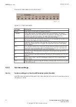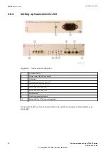
Every switch position for clock selection is represented by the four LEDs (1, 2, 4 and 8) on the
front panel as shown in Table
(X indicates a lit LED). The LEDs form a corresponding binary-
value for each switch position.
Table 26: LEDs indicating clock synchronization configuration by the rotary switch
LED 1
LED 2
LED 3
LED 4
Function
(0H) External clock selected (slave mode)
X
(1H) Internal clock selected (master mode)
5.6.5
Power-up and LED statuses with transceiver 21–219
GUID-52777300-7C19-47E4-BF9B-ED974E050D47 v1
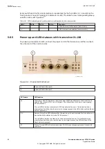
To power up transceiver 21–219, connect the power cord to the transceiver, and then connect
the other end of the cord to mains.
IEC07000246-1-en.vsdx
IEC07000246 V1 EN-US
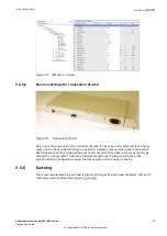
Figure 84: Channel LED indicators
1
Status LEDs for Channel 0
2
Status LEDs for Channel 1
LED name
LED function
LA
Local Alarm. Red LED indicates that transceiver 21-219 has detected a fault condition in
the C37.94 protocol (LOS = Loss Of Signal). The Yellow Alarm bit is set in the outgoing
C37.94 protocol.
The red LED is lit when transceiver 21-219 has detected an error. The indication has a
memory function. When the local error is no longer present, the LED blinks until the Reset
button is pressed.
RA
Remote Alarm. Red LED indicates that the remote unit has detected a fault condition, and
has set the Yellow Alarm bit in the C37.94 protocol.
The red LED is lit when the fibre-optic link has detected an error. The indication has a
memory function. When the remote error is no longer present, the LED blinks until the
Reset button is pressed.
ST
Status. The red LED is lit when transceiver 21–219 has set outgoing data on fibre-to-AIS
condition.
Section 5
1MRK 505 382-UEN E
Communication set-up
82
Communication set-up, 670/650 series
Application Guide
© Copyright 2017 ABB. All rights reserved
Содержание Relion 670 series
Страница 1: ...Relion 670 650 SERIES Communication set up 670 650 series Version 2 2 Application Guide...
Страница 2: ......
Страница 10: ...4...
Страница 99: ...93...

