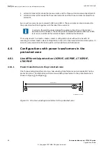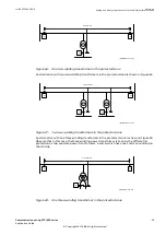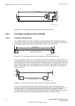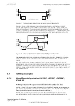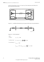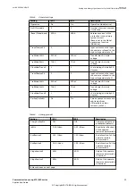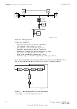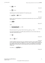
Notes:
1
IBase (set in GBASVAL) is the reference current of the line differential protection given in
primary Amperes. CT1 in terminal 1 has a ratio of 600/1 and that is why 600 A is chosen
for
IBase in this example.
2
Only one physical power transformer is included in the protected circuit. However, to
handle the situation with two CTs on the low-voltage side of the transformer, one more
fictitious power transformer is introduced. Thus, transformer A can be thought of as
being installed at CT2, and transformer B, which is identical to A, can be thought of as
being installed at CT3. Currents measured at CT2 and CT3 are internally separately
referred to the high-voltage side of the transformer by the multi-terminal differential
algorithm using the same transformation rule. This rule is defined by the power
transformer transformation ratio and its type (Yd1 in this example). If an in-line power
transformer is included in the protected zone, the protected power lines are usually on
the high-voltage side of the in-line power transformer. The differential algorithm always
transforms the low-voltage side currents to the high-voltage side.
3
Earth faults on the Y-side of the transformer cause a zero sequence current that flows in
the Y-winding of the power transformer. This current does not appear outside the
transformer on the d-side, and is consequently not measured by CT2 and CT3. Thus, if Y-
side earth fault is external to the protected zone, zero sequence current that passes the
neutral point of the transformer appears as a false differential current. This can cause an
unwanted trip if zero sequence currents are not subtracted from all three fundamental
frequency differential currents.
4
Energizing the circuit means that the power transformer is energized at the same time. It
is assumed that this is always made from the high-voltage side, and the harmonic
restraint detects the inrush current and prevents a trip. Setting
IdMinHigh = 2.00 · IBase
is justified in this case since the transformer is large.
5
The interval when
IdMinHigh is active is set to 60 s because a power transformer is
included in the protected zone. As both IEDs process the same currents, both must have
the same value set for
IdMinHigh.
6
The unrestrained operate (differential) current limit should greater than the highest
through fault current. This current appears at a three-phase short circuit on the 33 kV
side of the transformer and can be calculated as:
220
2.75
3 (7.0 15.0 24.2)
Through
I
kA
=
=
×
+
+
EQUATION1423 V1 EN-US
(Equation 5)
With a safety margin of 20%:
1.2
1.2 2.75
3.30
5.50
0.6
0.6
Through
I
kA
kA
Idunre
Ibase
kA
kA
×
×
=
=
=
=
EQUATION1424 V1 EN-US
(Equation 6)
7
The cross-block logic should always be active when there is a power transformer in the
protected zone.
Setting example with a small tap transformer in the protected zone
A typical example is shown in Figure
1MRK 505 382-UEN E
Section 4
Analog and binary signal transfer for line differential protection
Communication set-up, 670/650 series
35
Application Guide
© Copyright 2017 ABB. All rights reserved
Содержание Relion 670 series
Страница 1: ...Relion 670 650 SERIES Communication set up 670 650 series Version 2 2 Application Guide...
Страница 2: ......
Страница 10: ...4...
Страница 99: ...93...

