background image

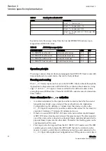
See the list of available measurands from the product-specific point list manuals.

3.3.5.3 

Selection of Class 2 frame

The Class 2 frame is selected with parameter 

Frame1InUse n

. The user can select

between the user-defined frame 0, standard frames 1 to 5, or IED-dependent frames 6
and 7. Selection of frames 0 to 7 is possible even if the IED does not produce all the
values required by the mentioned Class 2 frames. Values that are not available in the
IED is set to 0 in the selected Class 2 data frame.

Using of several Class 2 frames simultaneously

Using several Class 2 frames simultaneously is not a standard feature. However, it is
possible to define that the IED sends more than one Class 2 frame to the master.
Actually up to four Class 2 frames can be defined. The additional Class 2 frame
selections is defined in setting parameters 

Frame2InUse n

Frame3InUse

 and

Frame4InUse

. For example, if 

Frame1InUse

 is set to "Private frame 6" and

Frame2InUse

 is set to "User frame", the IED gives out Class 2 "Private frame 6" and

Class 2 "User frame" responses to every second Class 2 poll made by the master.

3.3.5.4 

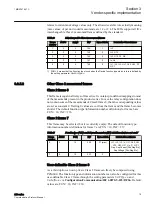
Scaling of Class 2 measurands

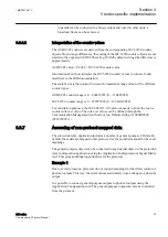
All Class 2 measurands can be rescaled separately using PCM600. The scale value
defines the highest value expressed by the IEC 60870-5-103 measurand. Values 1.2
and 2.4 are standard values but the IED can actually accept any value. For example,
scale 4.0 for IL1 enlarges the measurand range to -4.0*In…+4.0*In. The IEC
60870-5-103 measurand value is always signed, regardless if the original value is a
positive only value.

3.3.5.5 

Unsupported analog values

The IEC 60870-5-103 protocol does not support the transmission of counters or
integrated totals meaning cumulative values such as energy values. The IEC
Technical Committee 57 has defined the companion standard IEC 60870-5-102 for
this purpose.

3.3.5.6 

Measurand events and registration objects

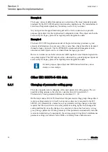
The relay contains some regular measurands that can be received as ASDU 4 or
TypeID 4 change events through the Class 1 buffer. All these objects are disabled by
default. These objects can be located in the point list and enabled through PCM600.

Depending on the relay configuration, the internal fault record can register various
start current and voltage and maximum current and voltage values during a fault
situation. The fault reactance and distance to fault can also be registered, providing
that the relay variant supports the fault locator function. The fault record data is
available as ASDU 4 Class 1 objects. All these objects are disabled by default. These
objects can be located in the point list and enabled through PCM600.

Section 3

1MRS757647 C

Vendor-specific implementation

20

620 series

Communication Protocol Manual

Содержание Relion 620 Series

Страница 1: ...RELION PROTECTION AND CONTROL 620 series IEC 60870 5 103 Communication Protocol Manual...

Страница 2: ......

Страница 3: ...Document ID 1MRS757647 Issued 2019 06 19 Revision C Product version 2 0 FP1 Copyright 2019 ABB All rights reserved...

Страница 4: ...bed in this document is furnished under a license and may be used copied or disclosed only in accordance with the terms of such license Trademarks ABB and Relion are registered trademarks of the ABB G...

Страница 5: ...ted and communicate data and information via a network interface which should be connected to a secure network It is the sole responsibility of the person or entity responsible for network administrat...

Страница 6: ...concerning electrical equipment for use within specified voltage limits Low voltage directive 2014 35 EU This conformity is the result of tests conducted by ABB in accordance with the product standar...

Страница 7: ...ic counters 11 IEC 60870 5 103 process data 12 IEC 60870 5 103 data objects 12 Indications 12 ASDU 2 type fault number and relative time data 13 Configuring of IEC 60870 5 103 indications 13 Class 1 e...

Страница 8: ...Device function type 25 Device identification code 25 Time synchronization 26 Disturbance recorder file transfer 26 Disturbance recorder file directory ASDU 23 26 Disturbance recorder channel identifi...

Страница 9: ...s the communication system engineer or system integrator responsible for pre engineering and engineering the communication setup in a substation from a protection relay s perspective The system engine...

Страница 10: ...ployment guideline GUID 6087BB7C D675 413B B1CD C4FEEEED8EEB V2 EN Figure 1 The intended use of documents during the product life cycle Product series and product specific manuals can be downloaded fr...

Страница 11: ...nder certain operational conditions operation of damaged equipment may result in degraded process performance leading to personal injury or death Therefore comply fully with all warning and caution no...

Страница 12: ...ssages and monitored data names are shown in Courier font When the function starts the START output is set to TRUE This document assumes that the parameter setting visibility is Advanced Section 1 1MR...

Страница 13: ...pplication data 5 4 Definition and coding of application information elements 5 5 Basic application functions 5 6 Conformance testing guidelines 5 103 Companion standard for the informative interface...

Страница 14: ...roblems with older installations every available IEC 60870 5 103 process data point can be freely remapped with PCM600 All the mapped data is not in use by default 2 2 Documentation Address informatio...

Страница 15: ...overflows should be treated and reported ASDU type 2 data is generally supported This means the generation of a fault number and a relative time stamp for protection related Class 1 events Despite the...

Страница 16: ...o protocol instances is in use I3CLPRT EC_FRZ STATUS GUID B230DC02 9257 4A70 A16D 2FC4A9D35CD6 V1 EN Figure 2 Function block By default Instance 1 is active in the IED but needs to be set On by the Op...

Страница 17: ...frames and link errors The serial drivers COMn have their own diagnostic counters for lower level serial communication character error and link messages The COMn counters count all the messages on th...

Страница 18: ...ntical For a list of the available data objects see the point list manual 3 3 2 Indications The IEC 60870 5 103 standard defines indications to be of ON OFF type The value coding for indications is al...

Страница 19: ...tions Change GI assignment of indications Change ASDU type used by the indications Change the data coding value DPI representation four pole objects only Suppress falling edge Class 1 events non stand...

Страница 20: ...erflow operation in the IED The setting parameters are located in Configuration Communication IEC 60870 5 103 I3C0n parameter suffix n 1 or 2 depending on the instance Class1OvInd n takes the overflow...

Страница 21: ...0870 5 103 Class 1 data In older IED versions the LED object had only two positions Off and Alarm red The corresponding IEC 60870 5 103 Class1 LED data area shows DPI values off 01 for Off and values...

Страница 22: ...red maximum current and voltage values during a fault and fault locator registrations For example also tap changer position values can be obtained through TypeID 4 There is no internal prioritization...

Страница 23: ...be controlled ON If the IED is in local mode the remote CB controls are rejected 3 3 4 1 Circuit breaker control model Circuit breaker can only be controlled with DIRECT ON OFF commands This is due to...

Страница 24: ...and is rejected on link level Link NAK DFC 1 Remote command performed on a non existing object The command is rejected on link level Link NAK DFC 0 In the last two cases the DFC flag is used to distin...

Страница 25: ...the corresponding values are set as constant 0 Trailing 0 values are cut from the frame and the frame becomes shorter The default function type information number definitions for frame 6 are FUN 10 IN...

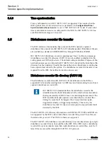
Страница 26: ...IEC 60870 5 103 measurand Values 1 2 and 2 4 are standard values but the IED can actually accept any value For example scale 4 0 for IL1 enlarges the measurand range to 4 0 In 4 0 In The IEC 60870 5...

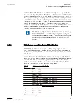
Страница 27: ...to collect registrations belonging to the same fault situation ASDU 4 events can easily fill up the Class 1 event buffer The fault record can for example be configured to register only after an operat...

Страница 28: ...esent IED real time Thereafter ASDU205 counter events are created into Class1 buffer Some alternatives for EC_FRZ activation A common alternative for the operation is that counters should be frozen an...

Страница 29: ...ll over value The roll over values can be defined through the Communication Management tool Scale value Default setting is 1000000000 999999999 1 3 3 7 Accessing of non protocol mapped data The protec...

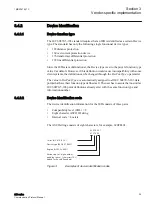
Страница 30: ...y protocol as regular protocol application data General purpose input object and OR function block may cause delays to time stamps 3 4 Other IEC 60870 5 103 data 3 4 1 Changing of parameter setting gr...

Страница 31: ...o all IEC 60870 5 103 data points that have their function type defined as 0 The user has to assure that no similar IEC 60870 5 103 point definitions already exist with the same function type and info...

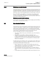
Страница 32: ...so unnecessary 3 5 1 Disturbance recorder file directory ASDU 23 The disturbance recorder files IEC 60870 5 103 identification in the IED is a sequential 16 bit number starting from 1 at IED reset and...

Страница 33: ...C 60870 5 103 protocol 3 5 2 Disturbance recorder channel identification IEC 60870 5 103 defines channels analog data and tags digital data to be transferred from a disturbance recorder file The IEC 6...

Страница 34: ...recorder channels can be selected from the disturbance recorder configuration settings Only the selected channels are included in the 60870 5 103 files 3 5 3 Disturbance recorder tags identification A...

Страница 35: ...eate up to 20 40 times more events during a fault compared to single function devices that were the basis for the IEC 60870 5 103 standard IEC 60870 5 103 has some limitations The protocol is defined...

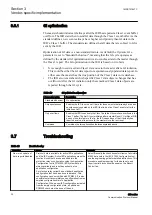
Страница 36: ...of a GI Only overflown Enables the IED to send only the Class 1 data that it knows have overflown in the Class 1 buffer The first GI cycle initiated after a master Reset CU or Reset FCB does not use...

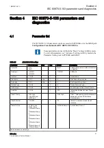
Страница 37: ...t delay 0 20 char 1 4 Start frame delay in chars End delay 0 20 char 1 4 End frame delay in chars DevFunType 0 255 1 9 Device Function Type UsrFunType 0 255 1 10 Function type for User Class 2 Frame U...

Страница 38: ...ndard frame 4 5 Standard frame 5 6 Private frame 6 7 Private frame 7 1 Not in use Active Class2 Frame 4 Class1OvInd 0 No indication 1 Both edges 2 Rising edge 2 Rising edge Overflow Indication Class1O...

Страница 39: ...r freezing energy counters 4 2 Monitored data Table 15 Protocol diagnostic counters I3C01 and I3C02 Attribute Values range Default Description Status False Communication inactive True Communication ac...

Страница 40: ...34...

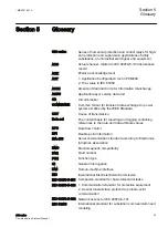
Страница 41: ...set The content basis for reporting and logging containing references to the data and data attribute values DFC Data flow control DPI Double point information EIA 485 Serial communication standard acc...

Страница 42: ...otection and Control IED Manager Reset CU Reset communication unit Reset FCB Reset flow control bit SOF Status of fault SW Software TEST Disturbance data recorded in test mode bit TM Disturbance data...

Страница 43: ...37...
Страница 44: ...ne 358 10 22 11 ABB Nanjing SAC Power Grid Automation Co Ltd No 39 Shuige Road Jiangning District 211153 Nanjing China Phone 86 25 69832000 Fax 86 25 69833000 www abb com mediumvoltage www abb com rel...

Отзывы: