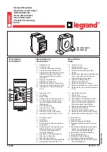
See the installation manual for more information about the case and
the plug-in unit.
Table 3:
Input/output overview
Std. conf. Order code digit
Analog channels
Binary channels
5-6
7-8
CT
VT
BI
BO
RTD
mA
A
AE / AF
AG
4
5
16
4 PO + 6
SO
-
-
FC
4
5
16
4 PO + 2
SO + 3
HSO
-
-
FE / FF
AD
4
5
12
4 PO + 6
SO
2
1
FE
4
5
12
4 PO + 2
SO + 3
HSO
2
1
C
AE / AF
AG
4
5
16
4 PO + 6
SO
-
-
FC
4
5
16
4 PO + 2
SO + 3
HSO
-
-
FE / FF
AD
4
5
12
4 PO + 6
SO
2
1
FE
4
5
12
4 PO + 2
SO + 3
HSO
2
1
D
BC / BD
AD
7
5
12
4 PO + 6
SO
-
-
FE
7
5
12
4 PO + 2
SO + 3
HSO
-
-
BE / BF
BA
7
5
8
4 PO + 6
SO
2
1
FD
7
5
8
4 PO + 2
SO + 3
HSO
2
1
2.4
Local HMI
The LHMI is used for setting, monitoring and controlling the protection relay. The
LHMI comprises the display, buttons, LED indicators and communication port.
Section 2
1MRS758272 B
REG615 overview
16
REG615
Application Manual


