manualshive.com logo in svg
background image

10 

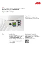
PositionMaster EDP300

 DIGITAL POSITIONER  |  CI/EDP300-EN REV. D 


3


Use in potentially explosive atmospheres in accordance with FM and CSA 


Change from one to two columns 


Note 

Further information on the Ex-Approval of devices can be found 
in the type examination certificates or the relevant certificates 
at 

www.abb.com/positioners


Product identification 


Depending on the type of explosion protection, an Ex name plate 
is attached next to the main name plate on the positioner. 
This indicates the level of explosion protection and the device's 
relevant Ex certificate. 


Ex marking 


FM 

FM Approval 

3043773 

Control drawing 

901305 

IS, CL. I, Div. 1, Gr. A, B, C, D, T4 or T6 

IS, CL. II, Div. 1, Gr. E, F, G, T4 or T6 

IS, CL. III, Div. 1, T4 or T6 

Class I Zone 0, AEx ia IIC, T4 or T6 

NI, Cl. I, Div. 2, Gr. A, B, C, D, T4 or T6 

NI. CI. II, Div. 2, Gr. E, F, G, T4 or T6 

NI, Cl. III, Div. 2, T4 or T6 

Class I Zone 2, IIC T4 or T6 

T4 Ta=(

40 to +85) °C; (

40 to +185) °F 

T6 Ta=(

40 to +40) °C; (

40 to +104) °F 

Type 4X 


CSA 

Certificate 2419437 

Control drawing 

901305 

CL I, Div. 1, Gr. A, B, C, D, T4 or T6 

CL II, Div. 1, Gr. E, F, G, T4 or T6 

CL III, Div. 1 

Class I Zone 0, AEx ia IIC T4 or T6 

CL I, Div. 2, Gr. A, B, C, D, T4 or T6 

CL II, Div. 2, Gr. E, F, G, T4 or T6 

CL III, Div. 2, T4 or T6 

Class I Zone 2, AEx nA IIC, T4 or T6 

T4 Ta=(

40 to +85) °C; (

40 to +185) °F 

T6 Ta=(

40 to +40) °C; (

40 to +104) °F 

IP64 


Mounting 


The installation, commissioning, maintenance and repair of 
devices in areas with explosion hazard must only be carried out 
by appropriately trained personnel. 
The operator must strictly observe the applicable national 
regulations with regard to installation, function tests, repairs, 
and maintenance of electrical devices. (e. g. NEC, CEC). 


Note 

Observe the device's applicable specifications and special 
conditions in accordance with the relevant certificate. 
 
•  Any manipulation in the device by users is not permitted. 

Only the manufacturer or an explosion protection specialist 
may modify the device 

•  The device may only be operated using instrument air that is 

free from oil, water and dust. 


Cable gland 

Limited temperature range of the M20 × 1.5 plastic cable gland 
for explosion protection variants. 
The permissible ambient temperature range of the cable gland is 

20 to 80 °C (

4 to 176 °F). When using the cable gland, make 

sure that the ambient temperature is within this range. The 
cable gland must be installed in the housing with a tightening 
torque of 3.8 Nm. When installing the connection of the cable 
gland and cable, check for tightness to ensure that the required 
IP rating is met.  


Содержание PositionMaster EDP300

Страница 1: ...and offers an outstanding price performance ratio Fully automatic determination of the control parameters and adaptation to the positioner allow for considerable time savings as well as optimum contro...

Страница 2: ...port and storage 14 Inspection 14 Transporting the device 14 Storing the device 14 Ambient conditions 14 Returning devices 14 6 Installation 15 Safety instructions 15 External position sensors 15 Mech...

Страница 3: ...Start automatic adjustment 40 9 Maintenance 41 10 Recycling and disposal 41 11 Supplemental specifications 41 Actuator travel 41 Housing 41 Transmission data and contributing factors 42 Seismic vibrat...

Страница 4: ...nd repairs to the product may only be performed if expressly permitted by these instructions Information and symbols on the product must be observed These may not be removed and must be fully legible...

Страница 5: ...to communicate information and data via a network interface It is operator s sole responsibility to provide and continuously ensure a secure connection between the product and your network or any othe...

Страница 6: ...d out only by persons whose training has included instructions on different types of protection and installation techniques concerned rules and regulations as well as general principles of zoning The...

Страница 7: ...on the housing must not be opened Only use cable glands which are approved for the type of protection and correspond to IP rating IP 6X Danger due to propagating brush discharge must be avoided Operat...

Страница 8: ...l Option modules Module for the emergency shutdown function Terminals 85 86 Temperature class T1 T6 Ui 30 V Pi 1 W Ci 5 3 nF Li negligibly small Module for analog feedback AO Terminals 31 32 Temperatu...

Страница 9: ...rgency shutdown function Terminals 85 86 Electrical values UN 30 V Module for analog feedback AO Terminals 31 32 Electrical values IN 22 mA UN 30 V Module for universal input UAI Terminals 21 22 Elect...

Страница 10: ...II Div 2 Gr E F G T4 or T6 CL III Div 2 T4 or T6 Class I Zone 2 AEx nA IIC T4 or T6 T4 Ta 40 to 85 C 40 to 185 F T6 Ta 40 to 40 C 40 to 104 F IP64 Mounting The installation commissioning maintenance...

Страница 11: ...rating IP 6X Danger due to propagating brush discharge must be avoided Operation in temperature class T6 During operation in temperature class T6 when the equipment is partially or fully depressurized...

Страница 12: ...for the emergency shutdown function Terminals 85 86 Temperature class T1 T6 Ui 30 V Pi 1 W Ci 5 3 nF Li negligibly small Module for analog feedback AO Terminals 31 32 Temperature class T1 T4 Temperat...

Страница 13: ...or H Slot1 Slot2 X X X 1 9 j k 3 4 5 6 7 l m n o p 8 2 ABB Automation Schillerstrasse 72 D 32425 Minden Made in Germany 1 Full type designation 2 Order code 3 Serial number 4 Special version 5 Hardwar...

Страница 14: ...metallic surfaces with a suited long term corrosion inhibitor Observe the relevant long term storage temperatures In principle the devices may be stored for an unlimited period However the warranty co...

Страница 15: ...egulations concerning the construction of technical installations External position sensors M10931 A B 1 2 3 6 5 4 1 2 7 6 5 4 1 EDP300 Control Unit 2 Connection cable 3 EDP300 Remote Sensor 4 Actuato...

Страница 16: ...or In this version the positioner is supplied without a position sensor The following points should be observed during installation Housing 1 EDP300 Control Unit contains the electronics and pneumatic...

Страница 17: ...necessarily need to run symmetrically to the longitudinal axis Note During installation make sure that the actuator travel or rotation angle for position feedback is implemented correctly Mounting on...

Страница 18: ...the lever moves within the operating range between the arrows 3 Hand tighten the screw 7 on the lever 4 Hold the prepared positioner with the mount bracket 1 still loose on the actuator so that the fo...

Страница 19: ...linkage 2 Decrease linkage Figure 10 Positioner linkage The scale on the lever indicates the link points for the various stroke ranges of the valve Move the bolt with the follower pin in the oblong ho...

Страница 20: ...chosen bolt position in the HMI menu in order to ensure optimum linearization The default setting is as follows M11031 1 2 3 5 4 1 Potentiometer lever 2 Actuator bolts 3 Valve stem 4 Valve yoke 5 Posi...

Страница 21: ...the positioner 1 Determine the mounting position parallel to actuator or at 90 angle 2 Calculate the rotational direction of the actuator right or left 3 Move the part turn actuator into the home pos...

Страница 22: ...main board in a hazardous area WARNING Risk of injury due to live parts When the housing is open contact protection is not provided and EMC protection is limited Before opening the housing switch off...

Страница 23: ...o two columns Connections for inputs and outputs Terminal Function comments 11 12 Analog input AI or field bus connection 81 82 Digital input DI 83 84 Digital output DO2 51 52 Limit alarm SW1 Option m...

Страница 24: ...one to two columns Connections for inputs and outputs Terminal Function comments 1 2 3 EDP300 Control Unit 51 52 Limit switch Limit 1 with proximity switch optional 41 42 Limit switch Limit 2 with pro...

Страница 25: ...vel Terminals 31 32 Signal range 4 to 20 mA split ranges can be parameterized Supply voltage two wire technology 24 V DC 10 to 30 V DC Characteristic curve rising or falling configurable Deviation 1 M...

Страница 26: ...ignal Safe position Active at 5 V DC There are two slots for the option modules Any combination of different option modules is possible However identical option modules cannot be combined Limit switch...

Страница 27: ...to approximately 6 mm 0 24 in 2 Connect the wires to the connecting terminals in line with the connection diagram Wire cross sectional areas Basic device Electrical connections 4 to 20 mA input Screw...

Страница 28: ...ire with the same cross section Rigid flexible wires 0 14 to 0 75 mm2 AWG26 to AWG20 Flexible with wire end sleeve no plastic sleeve 0 25 to 0 5 mm2 AWG23 to AWG22 Flexible with wire end sleeve with p...

Страница 29: ...ition feedback Digital position feedback Emergency shutdown module Universal input Housing 2 EDP300 Remote Sensor contains the position sensor and is suitable for mounting on linear or rotary actuator...

Страница 30: ...n accordance with the electrical connections and tighten the screws of the terminals so that they are hand tight Use wire end ferrules when connecting The electrical connections of the EDP300 Control...

Страница 31: ...ins the electronics and pneumatics along with the following options where applicable Analog position feedback Digital position feedback Emergency shutdown module Universal input Any position sensor 4...

Страница 32: ...r the housing cover and remove it 2 Position the option module so that the plug points to the right 3 Using a small amount of pressure guide the option module into the slot from the side and press it...

Страница 33: ...ew the option modules and remove them from the side 4 If present remove the mechanical position indication and screw off the shaft extension as well as the mechanical alarm signaling unit if applicabl...

Страница 34: ...e upper switching position Using a screwdriver adjust the metal tag of proximity switch 2 upper contact on the axis until contact is made i e just before it is inserted in the proximity switch The slo...

Страница 35: ...ctuator To eliminate the possibility of this occurring it is recommended to install a pressure compensation valve between the springless chamber and the supply air for these types of applications It e...

Страница 36: ...t off values End position 0 0 to 45 End position 100 55 to 100 7 Commissioning Safety instructions Note The electrical power supply and supply air pressure data indicated on the name plate must be com...

Страница 37: ...e relevant end positions 45 0 Pos Ang Check the end positions The angle of rotation is displayed in degrees Recommended range between 30 to 30 for linear actuator between 45 to 45 for rotary actuator...

Страница 38: ...o be operated with the housing cover open Menu navigation M10145 01 1 2 5 Menu 3 4 5 Exit Select 1 Operating buttons for menu navigation 2 Indication of menu designation 3 Indication of menu number 4...

Страница 39: ...anged on this level Operating modes menu In the operating modes menu the Auto Adjust function can be started for commissioning purposes You can also change the operating modes and switch to the config...

Страница 40: ...top left of the display Auto Adjust Full Auto Adjust Rotary Linear Exit 4 Use or to select Actuator type Select Rotary for rotary actuators Select Linear for linear actuators Note The Autoadjust Mode...

Страница 41: ...WEEE Directive 2012 19 EU and relevant national laws for example ElektroG Electrical Equipment Act in Germany The product must be supplied to a specialist recycling company Do not use municipal waste...

Страница 42: ...gn 1 to 10 g and 80 Hz Marine version 1 to 4 g and 100 Hz EDP300 and remote design control unit 1 to 10 g and 100 Hz for remote design position sensor freely configurable with 20 reference points Seis...

Страница 43: ...Company Address Contact person Telephone Fax Email Device details Type Serial no Reason for the return description of the defect Was this device used in conjunction with substances which pose a threat...

Страница 44: ...44 PositionMaster EDP300 DIGITAL POSITIONER CI EDP300 EN REV D 13 Appendix Control Drawing 901305...

Страница 45: ...PositionMaster EDP300 DIGITAL POSITIONER CI EDP300 EN REV D 45...

Страница 46: ...46 PositionMaster EDP300 DIGITAL POSITIONER CI EDP300 EN REV D 13 Appendix Control Drawing 901305...

Страница 47: ...PositionMaster EDP300 DIGITAL POSITIONER CI EDP300 EN REV D 47...

Страница 48: ...48 PositionMaster EDP300 DIGITAL POSITIONER CI EDP300 EN REV D 13 Appendix Control Drawing 901305...

Страница 49: ...PositionMaster EDP300 DIGITAL POSITIONER CI EDP300 EN REV D 49...

Страница 50: ...50 PositionMaster EDP300 DIGITAL POSITIONER CI EDP300 EN REV D Trademarks HART is a registered trademark of FieldComm Group Austin Texas USA...

Страница 51: ...PositionMaster EDP300 DIGITAL POSITIONER CI EDP300 EN REV D 51 Note...

Страница 52: ...EDP300 EN Rev D 09 2018 We reserve the right to make technical changes or modify the contents of this document without prior notice With regard to purchase orders the agreed particulars shall prevail...

Отзывы: