55
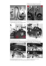
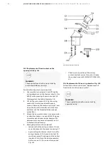
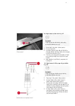
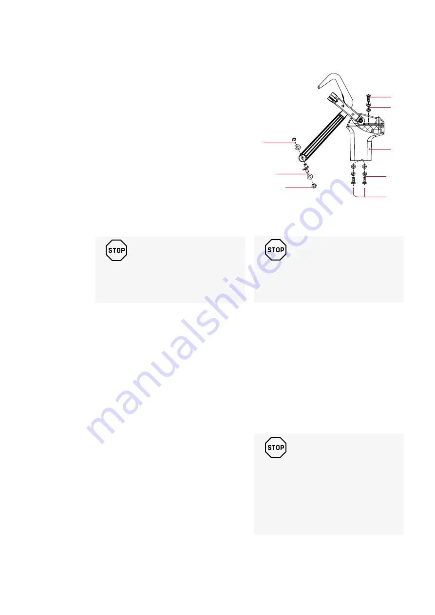
19.2 Pivot side support insulator.
Fig. 111
Detach the main contact with contact knives
according to item 46.0 point 2.
1. Unscrew 2.5 and detach the insulator,
2. Attach the new insulator to the frame by the
two self-tapping screws in case of DMC
(BMC) insulators or standard metric screws
in case of epoxy insulators (2.5).
For correct torque see Fig. 111.
Note the washer and spring washer for the
screws.
Attach the main contact with the contact knife to
the top of the insulator and adjust according to
item “Replacement of contact knife with draw
bar”.
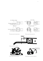
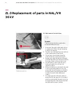
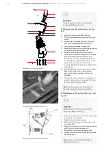
19.1 Replacement of contact knife with draw bar
Fig.111.
Switch-disconnector in open position with both
the operating springs uncharged:
1. Remove the circlips 2.1 attaching the draw
bar to the main shaft (eccentric bolt not to be
loosened).
2. Unscrew the screw(s) 2.2 attaching the main
contact to the insulator. Remove the fixed
contact with the contact knife and draw bar
(1 pc screw on 12 kV and 2 pcs screws on 24
kV).
3. Attach the new main contact with the contact
knife and draw bar to the insulator.
4. Grease the new contact knife with ISOFLEX
TOPAS NCA 52 and check carefully that it
enters the fixed main contact correctly, and
also that the arcing knife moves freely in the
arcing chamber when closing and opening
(the arcing knife does not have the same
position related to the contact knife during
the closing and opening movement). The
contact knife must rotate firmly at the pivot
point, but without jerking.
5. Attach the draw bar to the main shaft by the
eccentric bolt 2.3 and secure with washer and
circlips 2.1.
6. The depth of the engagement between the
fixed and the moving contact can be
adjusted by the eccentric bolt 2.3 or by
moving the insulator 2.
R EP L AC EM EN T O F PA R T S (1 2- 24 K V )
—
111 Support insulator with knife complete
_
WARNING!
These operations shall be carried out by
authorised ABB service only!
_
WARNING!
These operations shall be carried out by
authorised ABB service only!
_
CAUTION!
In case of complete contact (with
current knife) mounted to the support
insulator with inserts, screw shall be
tightened to 15 Nm torque (Fig. 111),
additionally lubricate using glue
eg LOCTITE 2701.
1 / 1
1:5
A4
Sheet No.
Format
Language
Scale
Subtitle
Type
Derived from
Name
Date
Location
Revision
Drawn
Checked
Approved
EC No.
EN
Drawing status
Title
Drawing No.
Responsible
ABB Switzerland Ltd
1971848.92 mm
22.86 kg
Weight
Material
f
m
c
v
H
L
K
PROPRIETARY AND SECRET INFORMATION The information contained in this document has to be kept stric
tly confidential.
Any unauthorized use, reproduction, distribution or disclosure
to third parties
is strictly forbidden. ABB reserves all rights regarding Intell
ectual Property Rights.
Thread Quality Tolerance
"6g-6H" ISO 965
ISO 2768 T.1 Lengths and Angle
ISO 2768 T.2 Geometrical Tolerances
Surface
Surface code
Coord. punching N.C.Mach.
and unfold JS11
Standard Tolerances for Machining and Forming
4
2
3
1
4
A
B
C
D
E
F
A
1
2
3
B
© Copyright
ABB. All rights reserved.
2016
Group Technology Management
M. Mańkowski
PL-PSY
03.03.2020
15 Nm
2.2
2.4
2.5
32 Nm
2.3
2.1
15 Nm

