


41-748.31B
13
KLF-1 Loss-of-Field Relay
such that the contacts will just close. De-ener-
gize the relay. The moving contact should return
to open position against the right-hand stop.
3) Impedance Check
a.
Adjust voltage to be 50 volts.
For current lagging 90° the impedance unit
should close its contacts at 2.60 - 2.76
amp. Reverse current leads, the imped-
ance unit should close its contacts 8.1 - 8.6
amperes.
b.
Reverse the links in the middle tap block to
-T
C
position (Horizontal). Apply current of
8.6 amps. The contacts should stay open.
Reverse current leads to original position.
The contacts should open when current is
increased above 8.1 amperes and
reduced below 2.8 Amps.
Set links back to +T
C
position (vertical).
Change S
A
and S
C
to setting “2”. Keeping
voltage at 50 volts, 90° leading, check
pickup current. It should be 1.30 - 1.40
amperes. Now set the phase shifter so that
voltage lags the current by 90°. Impedance
unit should trip now at 4.05 - 4.3 amperes.
c.
Change S
A
, S
C
= 3. Check pickup. It
should be 2.70 - 2.90. Reverse current
leads. Pickup should now be .87 - .93
amp.
D. Directional Unit (Top Unit)
1. Contact Gap Adjustment
The spring type pressure clamp holding the
stationary contact in position should not be
loosened to make the necessary gap adjust-
ments.
With moving contact in the open position,
i.e., against right stop on bridge, screw in
stationary contact until both contacts just
make. Then screw the stationary contact
away from the moving contact 3/4 of one turn
for a contact gap of .22”.
2.
With relay de-energized adjust the restraint
spring so that contact arm just floats.
3.
Maximum Torque Angle Check
With 50 volts and 5 amperes applied, vary
the phase shifter to obtain the two angles
where the moving contacts just close. These
two angles (where torque reverses) should
be where the current leads the voltage by
313°
±
4° and 133°
±
4°. Readjust the bottom
resistor located in the rear for correct read-
ing.
4.
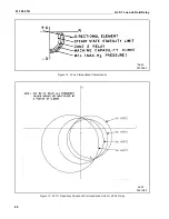
Sensitivity Adjustment
Apply 1.0 volt to terminals 4 and 6. Observ-
ing polarities as per schematic, apply 5
amperes current leading the voltage by 43°,
the spiral spring is to be adjusted such that
the contacts will just close. The spring type
clamp holding the spring adjuster should not
be loosened prior to rotating the spring
adjuster. The adjustment of the spring is
accomplished by rotating the spring adjuster
which is located on the underside of the
bridge. The spring adjuster has a notched
periphery so that a tool may be used to
rotate it. Plug Adjustment for Reversing of
Spurious Torques
a.
Set T
C
= 0.0. Connect a heavy current
lead from T
A
center link to terminal 8.
b.
Short circuit terminals 4 and 6.
c.
Screw in both plugs as far as possible
prior to starting the adjustment.
d.
Apply 80 amps only momentarily, and
the directional unit need not be cooled
during initial rough adjustment. But, the
directional unit should be cool when final
adjustment is made.
e.
When relay contact closes to the left,
screw out the right-hand plug until spuri-
ous torque is reversed.
f.
When plug adjustment is completed
check to see that there is no closing
torque when relay is energized with 40
amps and voltage terminals 4 and 6
short-circuited.
E. Undervoltage Unit (Lower Unit)
NOTE: The moving contact is in closed position
to the left when de-energized.


