


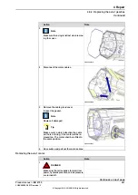


Concluding procedure
Note
Action
See
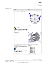
Performing a leak-down test on
Perform a leak-down test.
1
See procedures in
.
Refit the motor of the axis in question.
2
See procedures in
Refill oil in the gearbox in question.
3
Axis Calibration is described in
with Axis Calibration method on page 805
Re-calibrate the robot.
4
General calibration information is included
in section
.
DANGER
Make sure all safety requirements are met
when performing the first test run. These
are further described in
cause injury or damage on page 27
.
5
636
Product manual - IRB 8700
3HAC052853-001 Revision: F
© Copyright 2015-2018 ABB. All rights reserved.
4 Repair
4.8.1 Replacing the hub
Continued
Содержание IRB 8700 Series
Страница 1: ...ROBOTICS Product manual IRB 8700...
Страница 2: ...Trace back information Workspace R18 1 version a12 Checked in 2018 03 27 Skribenta version 5 2 025...
Страница 16: ...This page is intentionally left blank...
Страница 824: ...This page is intentionally left blank...
Страница 838: ...This page is intentionally left blank...
Страница 840: ...This page is intentionally left blank...
Страница 846: ......
Страница 847: ......


