


USER MANUAL
| ICOS | INSTRUCTIONS | UM/ICOS-EN REV. B.2
64
Appendix B:
Wireless Router Setup
A GL-MT300N-V2 Mini Smart Router is provided for use when the Local Area Network (LAN)
is not available. When Wi-Fi is
ON
, the analyzer will obtain a Dynamic Host Configuration
Protocol (DHCP) address from the router. The user can plug any Windows computer into
the same broadband router to access the data directory.
The router is pre-configured and assigns an IP address to its’ specific analyzer.
To use the wireless router:
1.
Connect the provided GL-MT300N-V2 Mini Smart Router:
a.
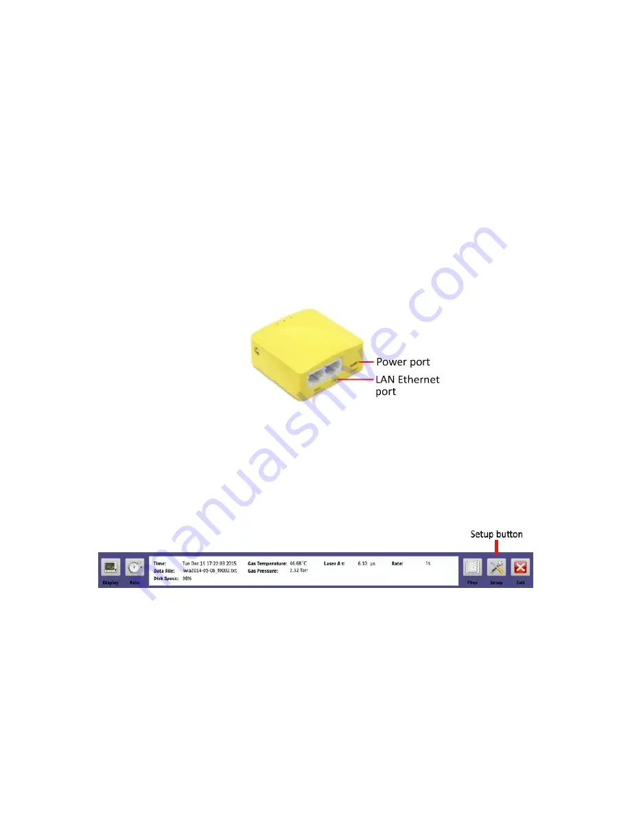
Connect the white cable from the Power port of the router to a USB port on
the analyzer. (Figure below)
b.
Connect the provided Ethernet cable from the analyzer to the LAN port on
the wireless router. (Figure below)
Figure 50: GL-MT300N-V2 Mini Smart Router
2.
Reboot the analyzer.
3.
The analyzer IP address will be in the format
192.168.8.XXX,
and will be displayed on
the
Time/Files
screen. (Figure 52) To access this screen, press the
Setup
button on
the
User Interface Control Bar
. (Figure 51)
Figure 51: Setup button on the User Interface Control Bar


