Type HCB-1 Pilot Wire Relay System
41-971.3M
7
(I
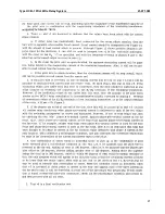
A2
is the phase A negative sequence current):
But:
So:
Equ. (6)
For T = 4
I
S
= 0.5
4.2.
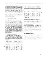
NOMINAL PICKUP (All Relays)
The nominal pickup, I
nom
, is defined as
Equ. (7)
Where
I
nom
= total internal fault current
K
= number of relays (2 or 3)
I
S
= single-relay pickup with pilot
wire disconnected (see above)
0.2
T
.2
I
A
1
–
.46
I
A
2
4.9
I
A
0
+
+
=
I
A
1
0.2
T
5.2
-----------
I
A
2
I
A
0
=
=
=
I
S
I
A
1
I
A
2
I
A
0
+
=
=
= 3
I
A
1
0.2
T
(
)
3
( )
I
S
3
I
A
1
0.2
T
3
×
(
)
5.2
-------------------------
0.12
T
(A-G Fault)
=
=
=
I
nom
KI
S
=
For example, in the previous example or a phase-A-
ground fault, the single-relay pickup was determined
as I
S
= 0.5 ampere for 4CH taps with the pilot-wire
open. For a two-terminal line, the nominal pickup for
a phase-A-to-ground fault (4CH taps) is:
4.3.
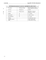
MINIMUM TRIP (All Relays)
With equal inputs to all relays and zero pilot-wire
shunt capacitance, the relays will operate at their
nominal pickup point. The minimum trip points will
vary somewhat from nominal value, depending on
the pilot-wire constants and the magnitude and
phase angle of the various relay input currents. For
example, Figure 6 shows the relay operating points
for a two-terminal line, assuming input current one
relay only.
An example of the characteristics with various cur-
rent distributions shown in Figure 6. The filter output
voltage, V
F
, of each relay, as defined by equation (1)
must be in phase or 180 degrees out-of-phase, in
order for Figure 7 to apply.
4.4.
INSULATING TRANSFORMER
Unless otherwise noted, all characteristics presented
include an insulating transformer with each relay.
Two ratios are available: 4/1 and 6/1. The high volt-
age side (H1-H4 Terminals) is connected to the pilot-
wires.
I
nom
A
to
G
(
)
0.5
0.5
2
×
1.0
ampere
=
=
=
Sub 4
183A61
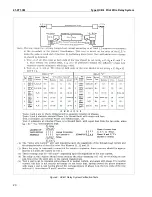
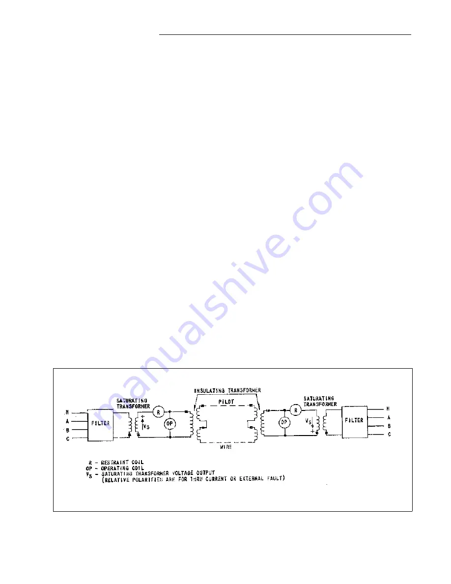
Figure 4. Simplified External Schematic of the HCB-1 Relay System
Содержание HCB-1
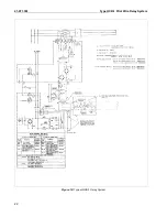
Страница 2: ...41 971 3M Type HCB 1 Pilot Wire Relay System 2 Figure 1 Type HCB 1 Relay Without Case Front View ...
Страница 3: ...Type HCB 1 Pilot Wire Relay System 41 971 3M 3 Figure 2 Type HCB 1 Relay Without Case Rear View ...
Страница 19: ...Type HCB 1 Pilot Wire Relay System 41 971 3M 19 THIS SPACE RESERVED FOR NOTES ...
Страница 20: ...41 971 3M Type HCB 1 Pilot Wire Relay System 20 Figure 9 HCB 1 Relay System Verification Tests ...
Страница 21: ...Type HCB 1 Pilot Wire Relay System 41 971 3M 21 ...
Страница 22: ...41 971 3M Type HCB 1 Pilot Wire Relay System 22 Figure 10 Typical HCB 1 Relay System ...
Страница 23: ...Type HCB 1 Pilot Wire Relay System 41 971 3M 23 Sub 15 4810D98 ...
Страница 27: ...Type HCB 1 Pilot Wire Relay System 41 971 3M 27 THIS PAGE RESERVED FOR NOTES ...


