


41-971.3M
Type HCB-1 Pilot Wire Relay System
16
8.3.
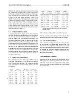
OPERATING UNIT
Check the relay minimum pick-up with the pilot-wires
disconnected from terminals H1 and H4 of the insu-
lating transformer, by energizing with I
79
current (ter-
minals 7 and 9). Pick-up current should be:
I
79
(MIN) = .53 T
±
5% amperes
Additional tests are recommended with the pilot-wire
connected as described under “Complete System
Test”.
9.0 COMPLETE SYSTEM TEST
At the time of the initial installation and at subsequent
maintenance periods, it is recommended that the fol-
lowing relay system checks be made, with the pilot-
wire connected.
9.1.
MINIMUM PICKUP
!
CAUTION
In making this test with the relay in place on
the switchboard, it is necessary to connect
the load box in the circuit between the relay
and the “HOT” side of the supply circuit. If
this precaution is not observed, it is possible
to cause a short circuit between the grounded
station service supply circuit and the ground
of the current transformer circuit.
The minimum pickup of each relay should be
checked before starting the system tests. With taps
4CH, as specified in Figure 9, and the pilot-wire cir-
cuit open on the high side of the insulating trans-
former, each relay should trip with I
AN
= 0.45 to 0.55
amp or with I
BC
= 2.10 to 2.15 amp.
With the pilot-wire connected, energize one relay
with I
AN
and determine the minimum pick-up of all
relays. Repeat this test by energizing the other relay
or relays. Record these values for future reference.
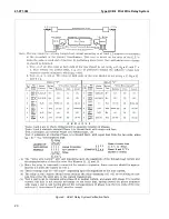
9.2.
VERIFICATION CIRCUIT TESTS
(Ref. Figure 9)
In performing these tests, the following procedure
should be used.
1.
Standard testing equipment is recommended for
permanent installation with the relays as shown
in Figure 8. If this equipment is not available, a
similar portable test should be set up using a
low-resistance ac milliammeter.
2.
Red handle flexitest case switch should be open
to interrupt the breaker trip circuit.
3.
A test crew is necessary at each substation with
a means of communication between them.
4.
When the test calls for delivering only specified
currents to the relay, it is necessary to use a thin
piece of insulating material in the ammeter test
jack. For example, test #5 of Figure 9 relay “N”.
To apply phase A to N current to the near relay
only, the switches associated with terminals 6, 7,
8, 9 of Figure 3 must be open. Opening switches
6 and 8 short circuits the current transformers for
phases B and C.
However, it is also necessary
to insert the insulating material in the amme-
ter test jacks associated with terminals 7 and
9 in order to break up the connection
between the filter in the relay chassis and the
grounded input circuits from current trans-
former circuits from current transformers in
phases B and C.
5.
To facilitate making test #2 of Figure 9 two
ammeter test plugs wired together with a foot or
two of flexible wire should be used. With these
two test plugs suitably wired together, one of
them may be shoved in the ammeter test jack
associated with terminal 9, Figure 3.
(This should
not be done until the switches for terminals 6 and
8 have been open, thus short circuiting the cur-
rent transformers involved)
. It is desirable to wire
the test plugs together such that when one is
shoved in the one ammeter test jack with the red
side up, and the other is shoved in the other
ammeter test jack with the black side up, it is
then known that the B and C phase currents to
the relay have been reserved at the input to the
chassis in line with test #2, Figure 9. After these
test plugs are properly inserted, it is then appro-
priate to close the switches associates with the
terminals 6 and 8, Figure 3, in order to remove
the short circuit from the current transformer sec-
ondaries.
Содержание HCB-1
Страница 2: ...41 971 3M Type HCB 1 Pilot Wire Relay System 2 Figure 1 Type HCB 1 Relay Without Case Front View ...
Страница 3: ...Type HCB 1 Pilot Wire Relay System 41 971 3M 3 Figure 2 Type HCB 1 Relay Without Case Rear View ...
Страница 19: ...Type HCB 1 Pilot Wire Relay System 41 971 3M 19 THIS SPACE RESERVED FOR NOTES ...
Страница 20: ...41 971 3M Type HCB 1 Pilot Wire Relay System 20 Figure 9 HCB 1 Relay System Verification Tests ...
Страница 21: ...Type HCB 1 Pilot Wire Relay System 41 971 3M 21 ...
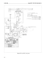
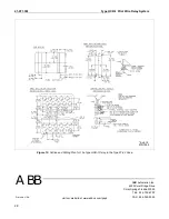
Страница 22: ...41 971 3M Type HCB 1 Pilot Wire Relay System 22 Figure 10 Typical HCB 1 Relay System ...
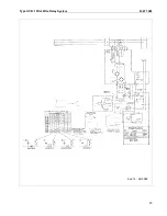
Страница 23: ...Type HCB 1 Pilot Wire Relay System 41 971 3M 23 Sub 15 4810D98 ...
Страница 27: ...Type HCB 1 Pilot Wire Relay System 41 971 3M 27 THIS PAGE RESERVED FOR NOTES ...


