


Electrical
connection
D184B097U02
FV4000-VT4/VR4 / FS4000-ST4/SR4
47
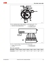
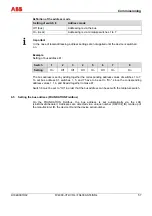
5.2.4 Separate
design
1.
Use the cable connected to the flowmeter sensor to make the electrical connection between
the flowmeter sensor and the transmitter.
2.
Unscrew the cover from the cable connection area at the rear of the transmitter.
Important
After switching off the supply power, wait t > 2 minutes before opening the flameproof
housing.
3.
Remove the insulation from the cable sheath, the shield and the wires as specified (see the
section titled "Cable connection area").
4.
Insert the bus cable into the cable connection area through the cable gland and fasten to the
cable grip on level with the shield to prevent accidental disconnection.
5.
Tighten the cable gland.
Warning - Potential damage to parts
If the bus cable is not fastened to the cable grip, the shield will not have a functional ground.
Furthermore, there is a risk of the cable being pulled completely out of the transmitter housing
should the strain fall below the required level, thereby interrupting the electrical connection.
The sheath of the bus cable must not be damaged. Otherwise, protection class
IP 67 for the flowmeter cannot be ensured.
6.
Connect the bare wires to the corresponding terminals (see the section titled "Cable
connection area").
7.
Screw on the cover for the cable connection area fully and fasten hand-tight. Make sure the
gaskets for the cover are seated properly.
Содержание FV4000-VT4
Страница 1: ...Operating Instruction D184B097U02 Vortex Flowmeter Swirl Flowmeter FV4000 VT4 VR4 FS4000 ST4 SR4 ...
Страница 125: ...Appendix D184B097U02 FV4000 VT4 VR4 FS4000 ST4 SR4 125 ...
Страница 126: ...Appendix 126 FV4000 VT4 VR4 FS4000 ST4 SR4 D184B097U02 ...
Страница 127: ...Appendix D184B097U02 FV4000 VT4 VR4 FS4000 ST4 SR4 127 ...
Страница 128: ...Appendix 128 FV4000 VT4 VR4 FS4000 ST4 SR4 D184B097U02 ...
Страница 129: ...Appendix D184B097U02 FV4000 VT4 VR4 FS4000 ST4 SR4 129 ...
Страница 135: ......


