


44
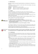
14.5.1.5 Power Connection Diagram
As an example, the following figure shows the typical connection diagram of phase current Rogowski
sensors and of optional CCT earth current transformer for a generic feeder; please refer to schematic
drawings 1VCD400060 for the withdrawable version and 1VCD400089 for the fixed version.
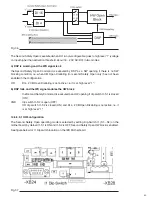
14.5.2 Single-Line diagrams
The Single-Line diagram selection enables you to define a typical application diagram between a
fixed and withdrawable CB and with or without an earthing switch on the cable side.
When one of the four defined applications is selected by the tick box, the digital inputs and
outputs (DI/O) are mapped according to selected predefined meanings (see chapter: Input /
Output Mapping). Refer to schematic drawings 1VCD400060 for complete meaning assignment of
withdrawable CB application. In this case all I/O are assigned and are not user configurable.
By ticking the “free” scheme, all available meanings can be assigned to the configurable I/O with
no restrictions.
As default, the free DI/O mapping will show the meanings assigned in the predefined diagram
selected before (e.g. by choosing “Free” after selecting “Withdrawable CB”. The DI 14, 15 will not
be used in DI mapping, while selecting “Free” after “Withdrawable CB + earthing switch” the
meanings “ES Open” and “ES Closed” will be assigned to DI 14,15).
Fig. 30
Generic feeder connection, overcurrent protections can be activated, residual current
can be directly measured
Содержание eVM1
Страница 1: ...eVM1 Installation and service instructions 12 17 5 kV 630 1250 A 16 31 5 kA ...
Страница 2: ...1 ...
Страница 76: ...74 Fig 66 Fig 67 ...
Страница 77: ...75 Fig 68 Fig 69 ...
Страница 110: ...108 Notes ...
Страница 111: ...1 ...


