


ABB | SACE Emax 2
56 | © 2017
ABB |
1SDH000999R0002 - ECN000058721 - Rev. B
Accessories | 2 - Circuit diagrams
2 - Circuit diagrams
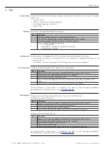
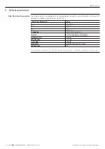
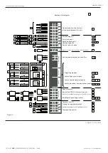
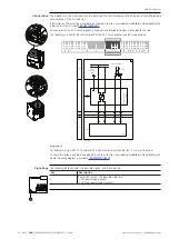
General wiring diagrams
The following is the wiring diagram of the circuit-breaker
, also available on the web site
http://www.abb.com/abblibrary/DownloadCenter/.
XK1
UI/L2
>
>
UI/L3
18
17
20
T34
T33
T24
TI/L1
TI/L3
TI/L2
UI/L1
Q
L1
L2
L3
11
12
9
10
19
21
22
XK1
T23
T14
T13
T32
T31
T22
T21
>>
>
>>
>>
2
14
13
XK1
T11
T12
K51
>
1
N
UI/N
15
16
T43
T44
EKIP G HI-TOUCH
EKIP G TOUCH
Q/27
Q/26
YO1
7
8
XK3
XK3
10
9
XK3
6
5
RTC EKIP
A1
A
T41
T42
8
7
TI/N
*
C)
EKIP DIP
EKIP TOUCH
EKIP HI-TOUCH
*
H)
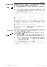
Diagram A - General diagram of the circuit-breaker
NOTE:
The diagram is shown in the following conditions:
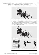
•
Circuit-breaker in withdrawable version (also valid for fixed version), open and connected.
•
Circuits de-energized.
•
Trip units not tripped.
•
Motor operator with springs discharged.
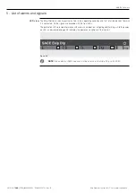
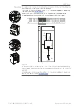
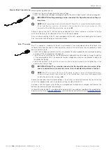
The following is the wiring diagram of the switch-disconnector:
L3
L2
L1
N
Q
B
A1
Diagram B - General diagram switch-disconnector
Continued on the next page


