background image

68 

EL3000

 CONTINUOUS GAS ANALYZERS  |  CI/EL3000-EN REV. B 


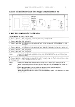
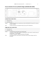
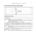
Gas connections for Limas23 with Magnos28 (Model EL3040) 


Limas23: Gas connections 

13

  Sample gas inlet 

14

  Sample gas outlet 

11

  Purge gas inlet for case 

12

  Purge gas outlet for case 

Design: 

 NPT female thread (stainless steel 1.4305/SAE 303) 

Connection of flexible tubes: Straight screwed fittings (PP) with nozzles for flexible tubes with 

inside diameter = 4 mm (supplied) 
Connection of pipelines: Threaded connections (not supplied) 

Note: 

The pressure sensor is connected internally in the outlet of the sample cell. 

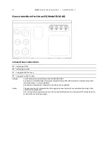
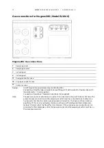
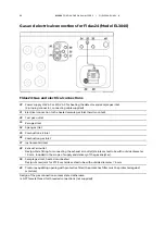
Magnos28: Gas connections 

1


Sample gas inlet 

2


Sample gas outlet 

Design: 

 NPT female thread (stainless steel 1.4305/SAE 303) 

Connection of flexible tubes: straight screwed fittings (PP) with nozzles for flexible tubes with 

inside diameter = 4 mm (supplied) 
Connection of pipelines: Threaded connections (not supplied) 

Note: 

The sample gas inlet of the Limas23 is connected ex works to the sample gas inlet of the   
Magnos28. 


Содержание EL3000 Series

Страница 1: ... ABB MEASUREMENT ANALYTICS COMMISSIONING INSTRUCTION EL3000 Continuous gas analyzers So smart they re simple Measurement made easy ...

Страница 2: ......

Страница 3: ...r 38 Housing purge 39 Dimensional drawings 41 Special requirements for the measurement of flammable gases 43 Installing the gas analyzer 44 Unpacking the gas analyzer 44 Installing the gas connections 45 Gas connections for Uras26 Model EL3020 47 Gas connections for Uras26 Model EL3040 49 Gas connections for Uras26 with Magnos206 Model EL3020 51 Gas connections for Uras26 with Magnos206 Model EL30...

Страница 4: ...al connections Analog output modules 96 Electrical connections Digital I O module 97 Electrical connections Modbus module 99 Electrical connections Profibus module 100 Connecting the signal lines 101 Connecting the power supply lines 102 Fidas24 Power supply line connection 103 Starting up the gas analyzer 104 Check the installation 104 Purge the sample gas path 105 Gas analyzer start up 106 ZO23 ...

Страница 5: ... supply of the gas analyzer Software tools Operating instructions Data sheets Technical information Certificates Internet You will find information on ABB Analytical products and services on the Internet at http www abb com analytical Service contact If the information in this operating instruction does not cover a particular situation ABB Service will be pleased to supply additional information a...

Страница 6: ...cation see page 7 2 Follow safety precautions see page 7 3 Prepare for the installation provide the requisite material see page 13 4 Unpack the gas analyzer see page 44 5 Check sample gas path seal integrity see page 119 6 Install the gas analyzer see page 81 7 Connect the gas lines see page 82 8 Connect the electrical leads see page 93 9 Check the installation see page 104 10 Purge the sample gas...

Страница 7: ...ed gas feed only in the EL3020 model not with Limas23 ZO23 Fidas24 may not be used for the measurement of flammable gases The explosion proof version of the gas analyzer with degree of protection II 3G see page 11 EL3040 model may be used for the measurement of non flammable gases and vapors in a hazardous environment NOTE The version for the measurement of flammable gases and vapors and the explo...

Страница 8: ...e as well as damage to other systems and devices Protective lead connection The protective lead ground should be attached to the protective lead con nector before any other connection is made Risks of a disconnected protective lead The device can be hazardous if the protective lead is interrupted inside or outside the device or if the protective lead is disconnected Risks involved in opening the c...

Страница 9: ...wing ignition attempts are unsuccessful The interior of the gas analyzer is not assigned to an explosion protection zone no explosive gas mixture can escape from it to the outside Conditions to be complied with by the end user The end user must comply with the following prerequisites and conditions to ensure safe operation of the gas analyzer The gas analyzer may be used for the measurement of fla...

Страница 10: ...ion gas supply to the gas analyzer in case of an instrument supply failure a visible or audible alarm must be triggered When measuring flammable gases it must be made sure that in case of a failure of the instrument air supply or of the analyzer module itself the sample gas supply to the analyzer module is shut off and the sample gas path is purged with nitrogen The unobstructed exchange of air wi...

Страница 11: ...s only intended for installation indoors The analyzers Uras26 Magnos206 Magnos28 and Caldos27 can be installed individually or as combinations of Uras26 with Magnos206 or Magnos28 or Caldos27 or oxygen sensor in the gas analyzer Operating the instrument under regular conditions cannot cause any ignita ble sparks arcs or impermissible temperatures inside the instrument Explosion proof with Spark fr...

Страница 12: ...c parts of the housing the gas analyzer has to be installed and operated in such a way that exposure to UV radiation is ruled out In the event that the housing is still damaged by UV radiation making it impossible to comply with degree of case protection IP65 the gas analyzer has to be shut down secured against re starts and it has to be repaired Replacing the battery The battery may not be replac...

Страница 13: ...O modules attached to the terminals of the I O modules Screwdriver required for attaching the electric lines in the mating plugs Micro porous filter see page 82 pre assembled DVD ROM Software tools and technical documentation Commissioning instruction Analyzer data sheet Fidas24 Mains lead see page 103 length 5 m with 4 pin socket connector and separate grounding connector for the power supply to ...

Страница 14: ...he connection are included in the scope of supply and delivery of the gas analyzer Flowmeter flow monitor Flowmeter or flow monitor with a needle valve for adjustment and mon itoring of the sample gas flow rate and purge gas flow rate if required Notes for the selection and use of flowmeters Measuring range 7 to 70 l h Pressure drop 4 hPa Needle valve open Recommendation Flowmeter 7 to 70 l h Part...

Страница 15: ...e more than 1 mm2 i e the cross section of the stranded wire may not be more than 0 5 mm2 The PZ 6 5 crimping tool of Weidmüller Co must be used for crimping the ferrules Max length of the RS485 leads 1200 m max transmission rate 19200 bit s Cable type 3 core twisted pair cable cable cross section 0 25 mm2 e g Thomas Betts Type LiYCY Max length of the RS232 leads 15 m Power supply lines If the sup...

Страница 16: ... housing is supported in a cabinet or rack with slide rails Short gas paths Install the gas analyzer as close as possible to the sampling location Install the gas conditioning and calibration modules as close as possible to the gas analyzer Adequate air circulation Provide for adequate natural air circulation around the gas analyzer Avoid heat build up Mount see page 81 several 19 inch housings wi...

Страница 17: ...indow the gas analyzer has to be installed and operated in such a way that mechanical damage to the display window with an energy exceeding 2 J is ruled out Protection against UV radiation Due to the low UV resistance of the plastic parts of the housing the gas analyzer has to be installed and operated in such a way that exposure to UV radiation is ruled out Housing design Model Housing design Deg...

Страница 18: ...upply from the other circuits by means of reinforced or double in sulation Functional extra low voltage PELV on the low voltage side Electromagnetic compatibility Interference immunity Tested to EN 61326 1 2013 Inspection severity Industrial environment fulfills at least the test requirements to table 2 of EN 61326 Emitted interference Tested to EN 61326 1 2013 Limit value class B for interference...

Страница 19: ... measuring flammable gases in general purpose envi ronment The special requirements for the measurement of flammable gas es see page 43 must be observed Flowing reference gas Gas inlet conditions as for sample gas Test gases Analyzer s Test gas for zero point calibration and single point calibration Test gas for end point calibration Uras26 with calibration cells automatic calibration N2 or air or...

Страница 20: ...rried out for the Caldos27 Uras26 oxygen sensor automatic calibration IR sample component free test gas with O2 concentration in an existing measuring range or ambient air Same moisture content as process gas Calibration cells or span gas Uras26 oxygen sensor manual calibration IR sample component free test gas with O2 concentration in an existing measuring range or ambient air Same moisture conte...

Страница 21: ...ed Test gases Analyzer s Test gas for zero point calibration and single point calibration Test gas for end point calibration Limas23 with calibration cells automatic calibration N2 or air or UV sample component free gas Calibration cells or test gas for each sample component Limas23 without calibration cells automatic calibration N2 or air or UV sample component free gas Test gas for each sample c...

Страница 22: ...the dew point of the sample gas NOTE The notes for calibrating must be considered Pressure sensor The pressure sensor is installed in the gas analyzer ex works It is located downstream the sample cell Gas connections see sections Gas connections Limas23 Model EL3020 see page 63 and Gas connections Limas23 Model EL3040 see page 64 ...

Страница 23: ... request Operation under elevated pressure A pressure sensor is required for pressure influence compensation Absolute pressure 1250 hPa An optional internal pressure sensor can be connected to the sample gas path Absolute pres sure 1250 hPa An external pressure sensor must be connected to the sample gas path The analyzer module is function tested for 5000 hPa in ternal pressure without damage Flow...

Страница 24: ... In order to avoid accumulations of explosive gas mixtures do not use air as a test gas for single point calibration when measuring flammable gas es Dew point The dew point of the test gases must be approximately the same as the dew point of the sample gas NOTE The notes for calibrating must be considered Pressure sensor The pressure sensor is installed in the gas analyzer as an option It is con n...

Страница 25: ...evated pressure A pressure sensor is required for pressure influence compensation Absolute pressure 1250 hPa An optional internal pressure sensor can be connected to the sample gas path Absolute pres sure 1250 hPa An external pressure sensor must be connected to the sample gas path Correction is done externally Flow 30 to 90 l h Changes in the sample gas flow rate should be avoided when using high...

Страница 26: ...In order to avoid accumulations of explosive gas mixtures do not use air as a test gas for single point calibration when measuring flammable gas es Dew point The dew point of the test gases must be approximately the same as the dew point of the sample gas NOTE The notes for calibrating must be considered Pressure sensor The pressure sensor is installed in the gas analyzer as an option It is con ne...

Страница 27: ...0 to 1250 hPa Operation under lower absolute pressure e g at altitudes above 2000 m on request Overpressure in the sample cell max 100 hPa Flow 20 to 90 l h Test gases Analyzer Test gas for zero point calibration and single point calibration Test gas for end point calibration Magnos27 Oxygen free process gas Process gas with known O2 concen tration Magnos27 with substitute gas calibration Oxygen f...

Страница 28: ...mple gas temperature pressure and flow rate should be main tained constant to such a degree that the fluctuation influence on the accu racy of measurement is acceptable see also Chapter Analyzer module oper ating data Corrosive gases The presence of corrosive gases and catalyst poisons e g halogens gases containing sulphur and heavy metal dusts causes faster aging and or or destruction of the ZrO2...

Страница 29: ...nd point must be considered Purge gas If a housing purge is selected only in IP54 version purging may only be carried out with air not with nitrogen as the ambient air serves as a refer ence gas Gas connections see sections Gas connections ZO23 Model EL3020 see page 75 and Gas connections ZO23 Model EL3040 see page 76 Installation and sample conditioning CAUTION The ingress of liquids into the ana...

Страница 30: ...act 6 2 way ball valve 1 7 2 way ball valve 1 8 Air filter 1 9 Gas analyzer 10 Flowmeter without needle valve with alarm contact 11 Purge gas cylinder with N2 1 12 Test gas cylinder with e g 2 ppm of O2 in N2 2 13 Test gas cylinder with 8 ppm O2 in N2 1 14 Pump 1 15 Needle valve 1 1 Option 2 A hard mounted test gas cylinder is normally adequate The annual check of the reference point can also be c...

Страница 31: ...bient air Bypass The gas analyzer is connected to a gas flow in the bypass at a constant flow rate approx 30 l h The needle valve is installed upstream of the branch to the gas analyzer and the bypass flowmeter downstream of the branch to the gas analyzer The gas analyzer takes 8 l h from the gas flow A surplus of approx 20 l h remains If several ZO23 analyzer modules are supplied with gas in para...

Страница 32: ... HCl HF SO2 NH3 H2S or other corrosive components the analyzer may be used only if the sample gas composition has been considered during analyzer configuration in the factory Flammable gases The analyzer is suitable for measuring flammable gases in general purpose environment The special requirements for the measurement of flammable gases see page 43 must be observed Test gases Analyzer Test gas f...

Страница 33: ...sure sensor The pressure sensor is installed in the gas analyzer ex works It is connected to a connection port via an FPM tube Gas connections see sections Gas connections Caldos27 Model EL3020 see page 77 and Gas connections Caldos27 Model EL3040 see page 78 ...

Страница 34: ...et conditions The outlet pressure must be the same as the atmospheric pressure Flammable gases The gas analyzer may be used for the measurement of flammable gases provided that the flammable portion does not exceed 15 vol CH4 or C1 equivalents Further sample gas inlet conditions The sample gas may not be explosive at any time The analyzer module must not be used for measurement of gases containing...

Страница 35: ...t be provided by the end user for this purpose ABB recommends the use of a bulkhead fitting with an integrated flow re strictor which must be installed in the combustion gas supply line This bulkhead fitting can be purchased from ABB Combustion gas H2 Part number 8329303 Combustion gas H2 He mixture Part number 0769359 Shut off valve in the combustion gas supply line A shut off valve must be insta...

Страница 36: ... to 250 l h End point calibration Quality Sample component or substitute gas component in ni trogen or synthetic air with concentration adjusted to the measuring range Inlet pressure pe 1000 100 hPa Flow 130 to 250 l h NOTE The notes for calibrating must be considered Gas connections See sections Gas and Electrical Connections for Fidas24 Model EL3020 see page 79 and Gas and Electrical Connections...

Страница 37: ...ment of flammable gases Other requirements The H2O dew point of the sample gas must be at least 2 C The oxygen sen sor may not be used if the sample gas contains the following components H2S compounds containing chlorine or fluorine heavy metals aerosols mercaptans alkaline components Integrated gas feed Flammable gases If the gas analyzer is equipped with an integrated gas feed it may not be used...

Страница 38: ...sensor connection and the sample gas outlet must be connected to each other via a T piece and short lines to ensure a precise pressure correction The lines must be as short as possible or if this is not practicable the line must have a sufficiently wide internal diameter at least 10 mm so that the flow effect is minimized If the pressure sensor connection is not connected to the sample gas outlet ...

Страница 39: ...ponent constituents in the purging gas can falsify the measurement result CAUTION Leaks may cause the purging gas to escape from the housing When ap plying nitrogen as purge gas appropriate precautionary measures must be taken against asphyxiation The purge gas flow must always be restricted upstream of the purge gas inlet If the purge gas flow is not restricted until after the purge gas out let t...

Страница 40: ...ousing purge in the Fidas24 The housing purge is implemented in the Fidas24 gas analyzer in such a way that a part approx 600 to 700 l h of the instrument air is conducted con tinuously through the housing as purging air This ensures that a flammable mixture cannot form in the housing in the event of a leak in the combustible gas feed path The housing purge is always active if compressed air is sw...

Страница 41: ...0 Dimensions in mm in 19 inch housing Model EL3020 with Magnos27 Dimensions in mm in NOTE Only the front view of the housing with its height differing from the standard dimension is depicted in this dimensional drawing Refer to the dimensional drawing above for other views and dimensions of the housing ...

Страница 42: ...42 EL3000 CONTINUOUS GAS ANALYZERS CI EL3000 EN REV B Wall mounting housing Model EL3040 Dimensions in mm in ...

Страница 43: ...east 3 cm The connection of the pressure sensor see page 38 must not be con nected to the sample gas feed path The sample gas lines and connections have to be made in stainless steel Prior to using the gas analyzer the corrosion resistance against the pre sent sample gas must be tested Commissioning of the gas analyzer The sample gas feed path must be purged see page 105 with inert gas before the ...

Страница 44: ...ply and delivery see page 13 from the shipping box Ensure that the accessories do not get lost 2 Remove the gas analyzer from the shipping box together with the re spective protective packaging 3 Remove the protective packaging and place the gas analyzer in a clean location 4 Remove the adhesive packaging residues from the gas analyzer NOTES Keep the shipping box and the protective packaging for f...

Страница 45: ...page 61 Limas23 Model EL3020 see page 63 Model EL3040 see page 64 Limas23 with Magnos206 Model EL3020 see page 65 Model EL3040 see page 66 Limas23 with Magnos28 Model EL3020 see page 67 Model EL3040 see page 68 Magnos206 Model EL3020 see page 69 Model EL3040 see page 70 Magnos28 Model EL3020 see page 71 Model EL3040 see page 72 Magnos27 Model EL3020 see page 73 Magnos27 with Uras26 Model EL3020 se...

Страница 46: ... ever since it may have been affected during transport of the gas analyzer e g by strong vibrations we recommend that it is checked see page 119 before the instrument is commissioned at the installation site NOTE We strongly recommend that the tightness of the sample gas feed path is checked before the gas analyzer is mounted since the housing must be opened in the event of a leak ...

Страница 47: ... outlet Gas feed path 2 Design Screwed fittings with hose nozzles stainless steel 1 4305 SAE 303 for hoses with 4 mm inner diameter supplied 21 Sample gas inlet on the solenoid valve with the option Integrated gas feed with solenoid valve pump filter capillary tube and flow sensor 22 Test gas inlet Design Screwed fittings with hose nozzles PVDF for hoses with 4 mm inner diameter supplied Note The ...

Страница 48: ...e stainless steel 1 4305 SAE 303 for hose with 4 mm inner di ameter supplied 11 Sample gas inlet 12 Sample gas outlet with one sample cell 13 Sample gas outlet with two sample cells in series Design NPT female thread stainless steel 1 4305 SAE 303 for threaded connections not supplied Note The oxygen sensor the option Integrated gas feed and the version with separate gas feed paths are not possibl...

Страница 49: ... executed as flexible tubes or stainless steel pipes 1 not assigned 2 not assigned 3 Sample gas inlet 4 Sample gas outlet with one sample cell 5 Purge gas inlet for case 6 Purge gas outlet for case 7 not assigned 8 Sample gas outlet with two sample cells in series 9 Pressure sensor if internal gas lines are executed as stainless steel pipes 10 not assigned ...

Страница 50: ...d stainless steel 1 4305 SAE 303 Connection of flexible tubes straight screwed fittings PP with nozzles for flexible tubes with inside diameter 4 mm supplied Connection of pipelines Threaded connections not supplied Notes If the internal gas lines are flexible tubes the pressure sensor standard and the oxygen sensor option are internally connected as follows in the outlet of sample cell 1 with one...

Страница 51: ...ple gas outlet Gas feed path 2 Design Screwed fittings with hose nozzles stainless steel 1 4305 SAE 303 for hoses with 4 mm inner diameter supplied 21 Sample gas inlet on the solenoid valve with the option Integrated gas feed with solenoid valve pump filter capillary tube and flow sensor 22 Test gas inlet Design Screwed fittings with hose nozzles PVDF for hoses with 4 mm inner diameter supplied No...

Страница 52: ...read stainless steel 1 4305 SAE 303 for threaded connections not supplied Note The oxygen sensor the option Integrated gas feed and the version with separate gas feed paths are not possible Magnos206 Gas Connections 1 Sample gas inlet 2 Sample gas outlet Design NPT female thread stainless steel 1 4305 SAE 303 Connection of flexible tubes straight screwed fittings PP with nozzles for flexible tubes...

Страница 53: ...s lines executed as flexible tubes or stainless steel pipes 1 not assigned 2 not assigned 3 Sample gas inlet 4 Sample gas outlet with one sample cell 5 Purge gas inlet for case 6 Purge gas outlet for case 7 not assigned 8 Sample gas outlet with two sample cells in series 9 Pressure sensor if internal gas lines are executed as stainless steel pipes 10 not assigned ...

Страница 54: ... the internal gas lines are flexible tubes the pressure sensor standard and the oxygen sensor option are internally connected as follows in the outlet of sample cell 1 with one sample cell and with separate gas feed paths in the outlet of sample cell 2 with two sample cells in series If the internal gas lines are stain steel pipes the oxygen sensor and the version with separate gas feed paths are ...

Страница 55: ...ple gas outlet Gas feed path 2 Design Screwed fittings with hose nozzles stainless steel 1 4305 SAE 303 for hoses with 4 mm inner diameter supplied 21 Sample gas inlet on the solenoid valve with the option Integrated gas feed with solenoid valve pump filter capillary tube and flow sensor 22 Test gas inlet Design Screwed fittings with hose nozzles PVDF for hoses with 4 mm inner diameter supplied No...

Страница 56: ...hread stainless steel 1 4305 SAE 303 for threaded connections not supplied Note The oxygen sensor the option Integrated gas feed and the version with separate gas feed paths are not possible Magnos28 Gas connections 1 Sample gas inlet 2 Sample gas outlet Design NPT female thread stainless steel 1 4305 SAE 303 Connection of flexible tubes straight screwed fittings PP with nozzles for flexible tubes...

Страница 57: ...s lines executed as flexible tubes or stainless steel pipes 1 not assigned 2 not assigned 3 Sample gas inlet 4 Sample gas outlet with one sample cell 5 Purge gas inlet for case 6 Purge gas outlet for case 7 not assigned 8 Sample gas outlet with two sample cells in series 9 Pressure sensor if internal gas lines are executed as stainless steel pipes 10 not assigned ...

Страница 58: ...upplied Notes If the internal gas lines are flexible tubes the pressure sensor standard and the oxygen sensor option are internally connected as follows in the outlet of sample cell 1 with one sample cell and with separate gas feed paths in the outlet of sample cell 2 with two sample cells in series If the internal gas lines are stain steel pipes the oxygen sensor and the version with separate gas...

Страница 59: ...ple gas outlet Gas feed path 2 Design Screwed fittings with hose nozzles stainless steel 1 4305 SAE 303 for hoses with 4 mm inner diameter supplied 21 Sample gas inlet on the solenoid valve with the option Integrated gas feed with solenoid valve pump filter capillary tube and flow sensor 22 Test gas inlet Design Screwed fittings with hose nozzles PVDF for hoses with 4 mm inner diameter supplied No...

Страница 60: ...e thread stainless steel 1 4305 SAE 303 for threaded connections not supplied Note The oxygen sensor the option Integrated gas feed and the version with separate gas feed paths are not possible Caldos27 Gas connections 1 Sample gas inlet 2 Sample gas outlet Design NPT female thread stainless steel 1 4305 SAE 303 Connection of flexible tubes straight screwed fittings PP with nozzles for flexible tu...

Страница 61: ...s lines executed as flexible tubes or stainless steel pipes 1 not assigned 2 not assigned 3 Sample gas inlet 4 Sample gas outlet with one sample cell 5 Purge gas inlet for case 6 Purge gas outlet for case 7 not assigned 8 Sample gas outlet with two sample cells in series 9 Pressure sensor if internal gas lines are executed as stainless steel pipes 10 not assigned ...

Страница 62: ...f the internal gas lines are flexible tubes the pressure sensor standard and the oxygen sensor option are internally connected as follows in the outlet of sample cell 1 with one sample cell and with separate gas feed paths in the outlet of sample cell 2 with two sample cells in series If the internal gas lines are stain steel pipes the oxygen sensor and the version with separate gas feed paths are...

Страница 63: ...mas23 Gas connections 1 Sample gas inlet 2 Sample gas outlet Design Screwed fittings with hose nozzles stainless steel 1 4305 SAE 303 for hoses with 4 mm inner diameter supplied Notes The pressure sensor standard and the oxygen sensor option are connected internally in the outlet of the sample cell ...

Страница 64: ...s steel 1 4305 SAE 303 Connection of flexible tubes Straight screwed fittings PP with nozzles for flexible tubes with inside diameter 4 mm supplied Connection of pipelines Threaded connections not supplied Notes The pressure sensor standard and the oxygen sensor option are connected internally in the outlet of the sample cell As an option the pressure sensor can be connected directly to the connec...

Страница 65: ... Note The pressure sensor is connected internally in the outlet of the sample cell Magnos206 Gas connections 1 Sample gas inlet 2 Sample gas outlet Design NPT female thread stainless steel 1 4305 SAE 303 Connection of flexible tubes straight screwed fittings PP with nozzles for flexible tubes with inside diameter 4 mm supplied Connection of pipelines Threaded connections not supplied Note The samp...

Страница 66: ...eter 4 mm supplied Connection of pipelines Threaded connections not supplied Note The pressure sensor is connected internally in the outlet of the sample cell Magnos206 Gas connections 1 Sample gas inlet 2 Sample gas outlet 3 not assigned 4 not assigned Design NPT female thread stainless steel 1 4305 SAE 303 Connection of flexible tubes straight screwed fittings PP with nozzles for flexible tubes ...

Страница 67: ...d Note The pressure sensor is connected internally in the outlet of the sample cell Magnos28 Gas connections 1 Sample gas inlet 2 Sample gas outlet Design NPT female thread stainless steel 1 4305 SAE 303 Connection of flexible tubes straight screwed fittings PP with nozzles for flexible tubes with inside diameter 4 mm supplied Connection of pipelines Threaded connections not supplied Note The samp...

Страница 68: ...ith inside diameter 4 mm supplied Connection of pipelines Threaded connections not supplied Note The pressure sensor is connected internally in the outlet of the sample cell Magnos28 Gas connections 1 Sample gas inlet 2 Sample gas outlet Design NPT female thread stainless steel 1 4305 SAE 303 Connection of flexible tubes straight screwed fittings PP with nozzles for flexible tubes with inside diam...

Страница 69: ... 303 for hoses with 4 mm inner diameter supplied 21 Sample gas inlet on the solenoid valve with option Integrated gas feed with solenoid valve pump filter capillary tube and flow sensor 22 Test gas inlet Design Screwed fittings with hose nozzles PVDF for hoses with 4 mm inner diameter supplied Note The pressure sensor is installed as an option It is connected to the port 6 via an FPM hose The pres...

Страница 70: ... Connection of pipelines Threaded connections not supplied Note The pressure sensor is installed as an option It is connected to the port 13 via an FPM hose The pressure sensor connection and the sample gas outlet must be connected to each other via a T piece and short lines to ensure a precise pressure correction The lines must be as short as possible or if this is not practicable the line must h...

Страница 71: ...303 for hoses with 4 mm inner diameter supplied 21 Sample gas inlet on the solenoid valve with option Integrated gas feed with solenoid valve pump filter capillary tube and flow sensor 22 Test gas inlet Design Screwed fittings with hose nozzles PVDF for hoses with 4 mm inner diameter supplied Note The pressure sensor is installed as an option It is connected to the port 6 via an FPM hose The press...

Страница 72: ...Connection of pipelines Threaded connections not supplied Note The pressure sensor is installed as an option It is connected to the port 13 via an FPM hose The pressure sensor connection and the sample gas outlet must be connected to each other via a T piece and short lines to ensure a precise pressure correction The lines must be as short as possible or if this is not practicable the line must ha...

Страница 73: ...Model EL3020 Magnos27 Gas connections 1 Pressure sensor option 2 not used 3 Sample gas inlet 4 Sample gas outlet 5 Purge gas inlet analyzer 6 Purge gas outlet analyzer Design Screwed fittings with hose nozzles stainless steel 1 4305 SAE 303 for hoses with 4 mm inner diameter supplied ...

Страница 74: ...ess steel 1 4305 SAE 303 for hoses with 4 mm inner diameter supplied Uras26 Gas connections 1 Sample gas inlet 2 Sample gas outlet Design Screwed fittings with hose nozzles stainless steel 1 4305 SAE 303 for hoses with 4 mm inner diameter supplied Notes The pressure sensor standard is connected internally in the sample gas outlet of the Uras26 As an option the pressure sensor can be connected dire...

Страница 75: ...nnections The sample chamber is connected to the sample gas inlet connection via a stainless steel tube on the inlet side and to the sample gas outlet connection via an FPM hose on the outlet side 1 Sample gas inlet 3 mm Swagelok 2 Sample gas outlet NPT female thread for threaded connections not supplied ...

Страница 76: ... inlet connection via a stainless steel tube on the inlet side and to the sample gas outlet connection via an FPM hose on the outlet side 1 Sample gas inlet 3 mm Swagelok 2 Sample gas outlet 11 Purge gas inlet for housing 12 Purge gas outlet for housing Design of the gas connections unless stated otherwise NPT female thread for threaded connections not supplied ...

Страница 77: ...ot supplied 3 Sample gas outlet with the option Integrated gas feed connected ex works to 1 Sample gas inlet 4 Sample gas inlet with the option Integrated gas feed only with flow sensor without solenoid valve 6 Pressure sensor Design Screwed fittings with hose nozzles stainless steel 1 4305 SAE 303 for hoses with 4 mm inner diameter supplied 21 Sample gas inlet on the solenoid valve with option In...

Страница 78: ...s outlet 3 not assigned 4 not assigned 11 Purge gas inlet for case 12 Purge gas outlet for case 13 Pressure sensor Design NPT female thread stainless steel 1 4305 SAE 303 Connection of flexible tubes straight screwed fittings PP with nozzles for flexible tubes with inside diameter 4 mm supplied Connection of pipelines Threaded connections not supplied ...

Страница 79: ... 32 Test gas outlet 33 Zero gas inlet 34 Span gas inlet 35 Combustion air inlet 36 Combustion gas inlet 37 Instrument air inlet 38 Exhaust air outlet Design Male fitting for connecting the exhaust air outlet stainless steel tube with outside diameter 6 mm included in the scope of supply and delivery of the gas analyzer 39 Sample gas inlet heated or unheated Design Screw joint for PTFE or stainless...

Страница 80: ... 35 Combustion air inlet 36 Combustion gas inlet 37 Instrument air inlet 38 Exhaust air outlet Design Male fitting for connecting the exhaust air outlet stainless steel tube with outside diameter 6 mm included in the scope of supply and delivery of the gas analyzer 39 Sample gas inlet heated or unheated Design Screw joint for PTFE or stainless steel tube with outside diameter 6 mm 40 Pressure equa...

Страница 81: ...per hour Special requirements for the gas analyzer model EL3020 for the measurement of flammable gases An unimpeded exchange of air with the surroundings must be possible around the gas analyzer from beneath base plate and from behind gas connections The gas analyzer must not be put directly on a table The case apertures must not be closed The distance to adjacent built in components on the side m...

Страница 82: ...sample gas inlet and if required before the purge gas inlet in order to be able to adjust and monitor the gas flow rate Provide for gas line system purging Install a shut off valve in the sample gas line definitely recommended with pressurized sample gas in order to provide a means for purging the gas line system by feeding in an inert gas e g nitrogen from the gas sampling point Evacuate exhaust ...

Страница 83: ...pes through leak points in the gas paths in the instrument can cause fires and explosions also outside the gas ana lyzer The lines and fittings must be clean and free of any residues e g particles left over from manufacturing Contaminants can enter the analyzer and damage it or lead to false measurement results NOTES The installation of gas connections is described in section Installing the gas co...

Страница 84: ...er module via a pressure regulator 0 to 6 bar Combustion air connection Connect see page 79 the combustion air line to the combustion air inlet of the analyzer module via a pressure regulator 0 to 1 6 bar Combustion gas connection See section Fidas24 Connecting the combustion gas line see page 86 Test gas connection The test gas outlet is connected to the sample gas connection ex works If the test...

Страница 85: ... the medium can be up to 200 C Lay the exhaust air line with a downward gra dient The inside diameter of the exhaust line should be increased to 10 mm within no more than 30 cm from the exhaust outlet If a very long exhaust air line is used it s inside diameter must be much larger than 10 mm otherwise the pressure regulation in the gas analyzer may not work properly Do not conduct waste air via re...

Страница 86: ...cer 7 Install a flow restrictor in the combustion gas supply line which restricts the combustion gas flow to 10 l h of H2 or 25 l h of H2 He mixture This means that operation of the gas analyzer is safe even with a defect in the combustion gas feed path e g leaks 8 Install a shut off valve in the combustion gas supply line It is recom mended that a pneumatic valve is installed this valve must be c...

Страница 87: ...he heated sample gas line is connected directly to the sample gas inlet In this respect the correct seat of the O rings must be ensured and also that the sample gas tube is inserted all the way in into the sample gas connec tion Unused sample gas inlets If the analyzer module draws in the sample gas through the sample gas line the unused sample gas inlets must be sealed with the screw plugs screwe...

Страница 88: ... 1 Test gas outlet 2 Connection of test gas outlet sample gas connection 3 Electrical connection to the heated sample gas connection 4 Heated sample gas connection 5 Heated sample gas line example Remark One half of the cover of the heated sample gas connection has been removed in the picture ...

Страница 89: ...CI EL3000 EN REV B 89 Connection of the sample gas line to the heated sample gas connection Wall mount housing view from bottom right III 1 2 3 4 5 6 7 8 9 10 11 I II 19 inch housing view from top left 5 6 7 8 II III 9 10 11 1 2 3 4 I ...

Страница 90: ...ste gas tube Sample gas Connection of the sample gas line inlets on 19 inch housing on wall mount housing I from the rear from below II from above from the right III from below not possible the sample gas inlet must always be closed Maximum length of the sample gas line The maximum length of the heated sample gas line inside diameter 4 mm is 30 m Provide for sample gas line purging Install a shut ...

Страница 91: ...tion of the sample gas line The unheated sample gas connection has only one sample gas inlet If the sample gas is under positive pressure a T piece must be connected between the sample gas line and the sample gas inlet The free connection of the T piece must be connected to a exhaust gas discharge line so that no positive pressure builds up in the analyzer module Connection of the sample gas line ...

Страница 92: ...cket 7 Tapered ring 8 Compression fitting 9 Exhaust gas tube for 19 inch housing 10 Exhaust gas tube for wall mount housing Maximum length of the sample gas line The maximum length of the unheated sample gas line inside diameter 4 mm is 50 m Provide for sample gas line purging Install a shut off valve in the sample gas line definitely recommended with pressurized sample gas in order to provide a m...

Страница 93: ...xample of the I O modules equipment max 4 The actual equipment of the supplied gas analyzer can differ it is documented in the analyzer data sheet 3 Analog output module see page 96 4 Modbus module see page 99 5 Profibus module see page 100 6 Ethernet 10 100BASE T interface for configuration and software update and for transmission of the QAL3 data 7 Connection for equipotential bonding see page 1...

Страница 94: ...cable glands Type Use Recommendation Permissible cable diameter M20 Power supply 5 to 13 mm M25 Modbus Profibus 8 to 17 mm insert 5 x 4 mm M25 Network connections 8 to 17 mm M25 3x analog outputs 8 to 17 mm insert 3 x 7 mm M32 Digital inputs outputs 12 to 21 mm M32 Digital inputs outputs 12 to 21 mm ...

Страница 95: ...modules equipment max 4 The actual equipment of the supplied gas analyzer can differ it is documented in the analyzer data sheet 3 Analog output module see page 96 4 Modbus module see page 99 5 Profibus module see page 100 6 Ethernet 10 100BASE T interface for configuration and software update and for transmission of the QAL3 data 7 Connection for equipotential bonding see page 102 capacity of ter...

Страница 96: ...mpared to local protective ground potential 50 V work ing resistance max 750 Ω Resolution 16 bit The output signal may not be less than 0 mA Design 4 pole or 8 pole plug in terminal strip Please refer to the information about the requisite material see page 101 Terminal layout An analog output is allocated in the sequence of the sample components for each sample component The sequence of the sampl...

Страница 97: ...Floating double throw contacts max contact load rating 30 V 1 A The relays must always be operated within the specified data Inductive or capacitive loads are to be connected with appropriate protective measures freewheeling diodes for inductive and series resistors with capacitive loads Relays are shown in the unpowered state The unpowered state corresponds to the state in the event of a fault fa...

Страница 98: ...e 1 DO2 Alarm value 2 DO3 Alarm value 3 DO1 Alarm value 4 DO2 Alarm value 5 DO3 Alarm value 6 DO4 Alarm value 7 Alarm value 8 Alarm value 9 Alarm value 10 Measuring range switchover Measuring range feedback Sample component switchover Sample component feedback Bus DI 1 Bus DI 2 Bus DI 3 Bus DI 4 Bus DI 5 Bus DI 6 Bus DI 7 Bus DI 8 External failure 2 DI3 External maintenance request 2 DI4 1 if a pu...

Страница 99: ...ns Modbus module RS232 interface Pin Signal 2 RxD 3 TxD 5 GND Design 9 pole male Sub D plug RS485 interface Pin Signal 2 RTxD 3 RTxD 5 GND Design 9 pole female Sub D plug NOTE For detailed information on Modbus refer to the Technical Information EL3000 EL3060 EL3010 C Modbus ...

Страница 100: ...ence potential for VP 6 VP Supply voltage plus 5 V 7 P24 24 V output voltage plus max 0 2 A 8 RxD TxD N Receive send data N A line 9 not assigned Design 9 pole female Sub D plug MBP interface not intrinsically safe Pin Signal 1 2 Shield 3 4 not assigned Design 4 pole plug in terminal strip Please refer to the information about the requisite material see page 101 NOTE For detailed information on Pr...

Страница 101: ...Z 6 5 crimping tool of Weidmüller Co must be used for crimping the ferrules Max length of the RS485 leads 1200 m max transmission rate 19200 bit s Cable type 3 core twisted pair cable cable cross section 0 25 mm2 e g Thomas Betts Type LiYCY Max length of the RS232 leads 15 m The mating plugs socket housing for the plug in terminal strips on the I O modules are supplied Connecting the signal lines ...

Страница 102: ...eeder near the gas analyzer or a switched socket outlet in order to be able to disconnect all the power from the gas analyzer if required Mark the mains isolator in such a way that the assignment of the devices to be disconnected can be clearly recognized 3 Attach the mains lead to the power supply connection of the gas ana lyzer and fasten the connector by means of the bracket 4 Connect the other...

Страница 103: ...ating is automatically detected and switched The set voltage can be identified through two LEDs on the mains distribution card 115 230 V AC connection to the analyzer module 1 Ensure that the power supply feeder has an adequately dimensioned protective device circuit breaker 2 Install an easily accessible mains isolator in the power supply feeder near the gas analyzer or a switched socket outlet i...

Страница 104: ...ctly connected and laid 3 Are all signal lines see page 101 and power supply lines see page 102 correctly connected and laid 4 Are all devices needed for gas conditioning calibration and waste gas disposal correctly connected and ready for use 5 When measuring flammable gases Are the special requirements see page 43 being observed 6 When applying the explosion protected version in the degree of pr...

Страница 105: ...free of contamination e g corrosive gases and dust deposits during start up Another reason is to prevent any explosive gas air formations that may be present in the sample gas feed path or the wall mount housing from ignit ing when the power supply is activated Purge gas Nitrogen Purging of the gas feed path Purge gas flow max 100 l h duration approx 20 s Purging of the wall mount housing Purge ga...

Страница 106: ...witches over to the measured value display Example 4 Check the configuration of the gas analyzer and alter if necessary 5 After the warm up phase has ended the gas analyzer is ready to carry out measurements Duration of the warm up phase Uras26 approx hour without thermostat approx 2 hours with ther mostat Limas23 approx 2 hours Magnos206 approx 1 hour Magnos28 approx 1 hour Magnos27 approx 2 to 4...

Страница 107: ...cal zero feed ambient air wait and until the measured value has stabilized duration approx 2 hrs Meanwhile purge the test gas valves and the gas supply line with oxy gen free gas e g with nitrogen from a loop feeder or with sample gas flow rate 5 to 10 l h 3 Set reference point to 20 6 vol of O2 4 Feed span gas and wait until the measured value has stabilized dura tion max 2 hrs 5 Set end point va...

Страница 108: ...ample gas nozzle MGA Pressure in the combustion chamber outlet The pressures of the supply gases are set by means of the controlled variables To begin with any values can be displayed for the controlled variables The values are updated for the first time approx 10 s after se lecting the menu option and then approx every 10 s The pressure con trol continues to run in the background It may take some...

Страница 109: ...ssure regulators deviate the inlet pressures of the instrument air combustion air and combustion gas must be adjust ed 9 Instrument air use the external pressure regulator to set the controlled variable for outlet to approx 60 max 70 Controlled variable too high reduce pressure Controlled variable too low increase pressure The controlled variable for inlet depends on the sample gas flow rate 10 Co...

Страница 110: ...alyzer In this case the igni tion of the flame must be restarted in the Fidas Restart menu see page 116 The temperature of the flame is also displayed in this menu option the flame is regarded as on when the flame temperature is at least 30 C higher than the detector temperature The actual start up of the gas analyzer is concluded with the ignition of the flame NOTE New and still unused sample gas...

Страница 111: ...ion gas pressure 4 Check see page 118 the seal integrity of the combustion gas feed path 5 Turn on the sample gas supply CAUTION The gas analyzer and the analyzer module must be de energized before the connector of the 115 230 V AC power supply for heating the detector and the heated sample gas connection is connected or disconnected Otherwise the heating may be damaged The cover of the heated sam...

Страница 112: ... information on Modbus can be found in the technical information EL3000 Modbus and EL3010 C Modbus via TCP IP Setting up the communication between the gas analyzer and the computer Basically the following steps are required to set up the communication be tween the gas analyzer and computer 1 Check and set the TCP IP parameters in the gas analyzer and the com puter 2 Establish and test the Ethernet...

Страница 113: ...consists of EL3K and the last six positions of the MAC address example EL3KFF579A If the parameter DHCP is set to off the Ethernet configuration is reset to the standard configuration default IP address this will prevent the inad vertent assignment of an IP address from a DHCP pool Addresses The IP address IP address mask and IP gateway address must be obtained from the system administrator NOTE T...

Страница 114: ... termi nal layout 1 3 3 1 2 6 6 2 Connection via an Ethernet network twisted pair cable with RJ45 connect ors The cables are standard Ethernet cables and are not part of the scope of supply and delivery of the gas analyzer Test the Ethernet connection To test the Ethernet connection enter the following in the computer in Start Execute ping IP address with IP address IP address of the gas analyzer ...

Страница 115: ... connection Receiving configuration data After communication has been started the configuration data can be re ceived from the gas analyzer Menu File Receive Data or Sending configuration data After the configuration data been has edited it can be sent to the gas ana lyzer The configuration mode is active after an automatic cold restart of the gas analyzer Menu File Send Data or Saving configurati...

Страница 116: ... supply Ensure that the shut off valve in the combustion gas supply line is open 2 Set the combustion gas pressure to 1 1 x the normal pressure of the combustion gas i e approx 1 4 bar 3 Mark cylinder pressure indication on the high pressure gauge 4 Close the valve of the combustion gas cylinder 5 The display on the high pressure gauge it should not change measura bly in 10 minutes A measurable ch...

Страница 117: ...ication of a leak in the combustion gas path between the pressure reducer and the combustion gas inlet valve of the gas analyzer In this case the following measures are to be taken 1 Check the combustion gas line between the pressure reducer and gas analyzer with a leak detection spray A leak in this area must be remedied and another leak test must be performed before the gas analyzer is put into ...

Страница 118: ...om bustion gas inlet to combustion gas nozzle With a leak detector measurement principle thermal conductivity sniff all the connection points 2 Inspection of the combustion gas feed path with negative pressure in the detector after the combustion gas nozzle Connect zero gas at the sample gas inlet Envelope all the connection points one after the other with a small gas cloud containing hydrocarbons...

Страница 119: ...m T piece with shut off valve Air or nitrogen CAUTION If the seal integrity test is to be carried out with air and if flammable gas could be present in the sample gas feed path or is to be subsequently in troduced the sample gas feed path must be purged with nitrogen be forehand The seal integrity test can be carried out with nitrogen instead Checking the seal integrity of the sample gas feed path...

Страница 120: ...19 can be used as an alternative to the helium test To accomplish this increase the test pressure to a pe of approx 400 hPa 400 mbar and increase the test period to 15 minutes The maximum excess pressure pe 500 hPa 500 mbar Any time the gas path is opened it must then be purged prior to con necting the power supply This should remove any explosive gas air mixture in the gas path Purge gas Inert ga...

Страница 121: ...o be shut down secured against re starts and it has to be repaired In the event that the housing is damaged by UV radiation making it im possible to comply with degree of case protection IP65 the gas analyzer has to be shut down secured against re starts and it has to be repaired Replacing the battery The battery may not be replaced in an explosive atmosphere Only the original battery may be used ...

Страница 122: ... combination with mobile devices smartphone tablet etc Dynamic QR Code represents an innovative way of customer s communication which allows for instance improved case specific support by ABB resulting in an increased availability of analyzer assets Dynamic QR Code is compatible with the ABB application my Installed Base as well as with standard QR code scanner applications Handling The QR code is...

Страница 123: ...ct QR code with OK 3 Modify QR code resolution with if necessary 4 Scan QR code 5 Return to selection with Recommended QR code scanner applications ABB recommends the use of the following QR code scanner applications available free of charge for iOS and Android my Installed Base by ABB Download in App Store Download in Google Play QR Scanner by Kaspersky Download in App Store Download in Google Pl...

Страница 124: ...alyzer to standby operation see page 116 In case of corrosive and flammable gases set the gas analyzer to standby opera tion with detector purging 4 Shut off combustion air supply and combustion gas supply In the case of a long term shutdown carry out the following in addi tion 5 Shut off instrument air supply 6 Switch off the gas analyzer power supply 7 Remove the gas lines from the gas analyzer ...

Страница 125: ...uration at least 3 months 3 Pack the gas analyzer in an adequately sized box lined with shock absorbing material foam or similar The thickness of the shock absorbing material should be adequate for the weight of the gas analyzer and the mode of dispatch When shipping overseas additional ly line the box with a double layer of bitumen paper 4 Mark the box as Fragile Goods Ambient temperature Ambient...

Страница 126: ...panies Bear the following in mind when disposing of this product and its packaging This product is under the open scope of the WEEE Directive 2012 19 EU and relevant national laws The product must be supplied to a specialist recycling company Do not use municipal waste collection points These may be used for privately used products only in accordance with WEEE Directive 2012 19 EU If there is no p...

Страница 127: ......

Страница 128: ...otice With regard to purchase orders the agreed particulars shall prevail ABB does not accept any responsibility whatsoever for potential errors or possible lack of information in this document We reserve all rights in this document and in the subject matter and illustrations contained therein Any reproduction disclosure to third parties or utilization of its contents in whole or in parts is forbi...

Отзывы: