


EL3000
CONTINUOUS GAS ANALYZERS | CI/EL3000-EN REV. B
101
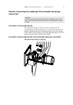
Connecting the signal lines
NOTES
Follow local regulations on installing and connecting electrical wiring.
Lay the signal lines separately from the power supply lines.
Lay analog and digital signal lines separately from each other.
Mark the cables or mating plugs in such a way that they can be clearly as-
signed to the corresponding I/O modules.
Requisite material
Select conductive material which is appropriate for the length of the
lines and the predictable current load.
Notes concerning the cable cross-section for connection of the
I/O modules:
The max. capacity of terminals for stranded wire and solid wire is
1 mm
2
(17 AWG).
The stranded wire can be tinned on the tip or twisted to simplify the
assembly.
When using wire end ferrules, the total cross-section may not be
more than 1 mm
2
, i.e. the cross-section of the stranded wire may not
be more than 0.5 mm
2
. The PZ 6/5 crimping tool of Weidmüller & Co.
must be used for crimping the ferrules.
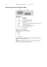
Max. length of the RS485 leads 1200 m (max. transmission rate
19200 bit/s). Cable type: 3-core twisted-pair cable, cable cross-section
0.25 mm
2
(e.g. Thomas & Betts, Type LiYCY).
Max. length of the RS232 leads 15 m.
The mating plugs (socket housing) for the plug-in terminal strips on the
I/O modules are supplied.
Connecting the signal lines
1
Only for the wall-mount housing (EL3040 model): Pass the cables
through the screwed cable glands (see page 94) and strip to a length of
approx. 18 cm.
M20 and M32: Remove the plugs from the insert; leave the ring in the
screwed cable glands for sealing and strain relief.
M25: Remove the plugs from the screwed cable glands. If required, slit
open the insert with drill holes from the accessories pack and press over
the cable; seal any open drill holes with dowel pins from the accessories
pack.
2
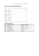
Connect the lines to the mating plugs as shown in the connection dia-
grams of the I/O modules:
Analog output module (see page 96)
Digital I/O module (see page 97)
3
Attach the mating plug to the plug-in terminal strips on the
I/O-modules.
Содержание EL3000 Series
Страница 2: ......
Страница 42: ...42 EL3000 CONTINUOUS GAS ANALYZERS CI EL3000 EN REV B Wall mounting housing Model EL3040 Dimensions in mm in ...
Страница 127: ......


