04-3275_OPM_ABB_CONCEPTPOWER_DPA_500kW_EN_REV-A.docx
Page 37/78 ABB
Modifications reserved
I/O PORTS
SD Card
Slot for the SD card
USB
USB connector
DC Input
Power supply connector (only needed if the RJ-45 cable is >75 & <100m)
UPS Input
RJ-45 connector
LED’s
UPS Status
GREEN: when the UPS is on inverter mode
RED: when the inverter is on alarm
Alarm
OFF: if no alarm present
RED: if unread alarm(s) present
BUTTONS
Reset
Press the “Reset” button to reset the remote panel
ON/OFF 1/2
Press “ON/OFF 1” + “ON/OFF 2”: Function disabled
Press “Reset” + “ON/OFF 1” buttons simultaneously, then release "Reset"
and hold the "ON/OFF 1" button for 10 seconds: Touch screen calibration
6.4.3
Start up and installation
When the UPS is energized, the display is automatically turned on. It is initiated for a few seconds and subsequently
the user is directed to the mimic diagram screen.
6.4.4
Navigation
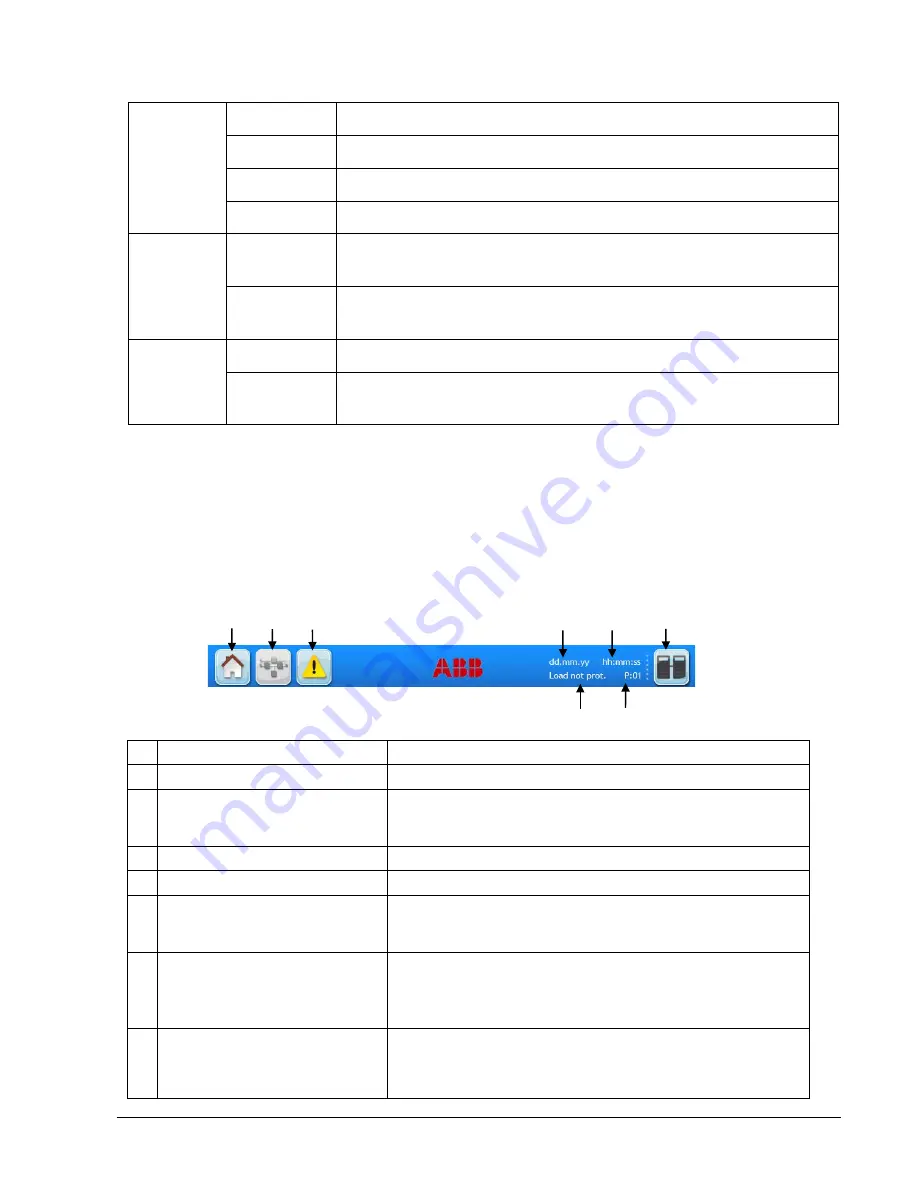
A few icons and some information are displayed in the top of every screen as indicated in the Figure 17.
Figure 18: Display header
A
Home
Directs the user to the navigation screen.
B
Mimic diagram
Directs the user to the mimic diagram screen.
C
Warning symbol
Warning symbol: Appears in case of alarms or events. Touching
this icon the alarm is silenced and the events screen is displayed.
D
Date
Adjustable in the user menu.
E
Time
Adjustable in the user menu.
F
Module selection
Directs the user to the module selection screen from where it is
possible to select the module and start the navigation (status and
measurements) on module level.
G
System status
Status of the load
System status: indicates that the user is in the system level
navigation.
Status of the load indicates if the load is protected, when the user
is in the module level.
H
UPS number
The numbering after the symbol
„P”
is sequential and represents
each module or frame in the system. For eg. “P01” indicates the
UPS number 01 in a parallel system. This information can be
configured by a service technician.
G
H
A
B
C
D
E
F


