


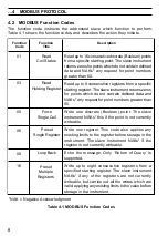


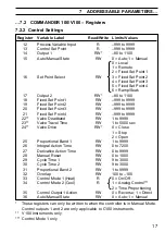

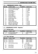


5
2
ELECTRICAL INSTALLATION…
2.3
Pull-up and Pull-down Resistors – Fig. 2.1 and 2.2
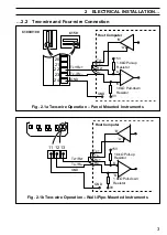
To prevent false triggering of slaves when the master (host computer) is inactive,
pull-up and pull-down resistors must be fitted to the RS422/485 interface in the host
computer – see Figs. 2.1 and 2.2.
Note. Resistors are normally connected to the interface by means of
hard-wired links or switches – refer to the manufacturer's instructions.
2.4
Termination Resistor – Fig. 2.3
For long transmission lines, a 120
Ω
termination resistor must be fitted to the last
slave in the chain – see Fig. 2.3.
2.5
Serial Connections – Figs. 2.1 to 2.3
Information.
•
Up to
10 slaves
can be connected to a single
RS422
adaptor card on a PC.
•
Up to
32 slaves
can be connected to a single
RS485
adaptor card on a PC.
The number of slaves can be increased if the driver's serial port permits.
Connections to the MODBUS serial board must be made as shown in Figs. 2.1 to
2.3. Connections on links with multiple slaves must be made in parallel, as shown
in Fig. 2.3. When connecting cable screens, ensure that no 'ground loops' are
introduced.
The maximum serial data transmission line length for both
RS422
and
RS485
systems is
1200m. The types of cable that can be used are determined by the total line length:
Up to 6m
–
standard screened or twisted pair cable.
Up to 300m
–
twin twisted pair with overall foil screen and an integral drain wire.
Up to 1200m
–
twin twisted pair with separate foil screens and integral drain wires.
Last Slave
Tx+
Tx-
Rx+
Rx-
GND
120
Ω
Termination
Resistor (Ext.)
Master
Rx+
Rx–
Tx+
Tx–
GND
Tx+
Tx–
Rx+
Rx–
GND
Host
Computer
First Slave
Fig. 2.3 Connecting Multiple Slaves


