

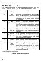

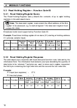

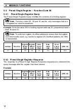


16
7
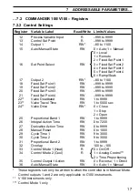
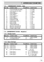
ADDRESSABLE PARAMETERS
7.1
COMMANDER 100/V100 – Coils
Coil No.
Variable Label
Read/Write
Limits/Values
01
Process Variable Fail State
R
1 = Failed
02
Remote Set Point Fail State
R
1 = Failed
03
A/D Converter Fail State
R
1 = Failed
06
Alarm State 1
R
1 = Active
07
Alarm Indicator 1
R
1 = On
08
Alarm State 2
R
1 = Active
09
Alarm Indicator 2
R
1 = On
14
Digital Input State
R
1 = On
15
Digital Output State
R
1 = On
16
Relay 1 State
R
1 = On
17
Relay 2 State
R
1 = On
19
On/Off Output 1 (Heat)
R
1 = On
20
On/Off Output 2 (Cool)
R
1 = On
30
Auto/Manual State
RW
0 = Auto; 1 = Manual
31
Control Action
W
0 = Reverse; 1 = Direct
32
Select Local Set Point
W
1 = Local
33
Select Remote Set Point
W
1 = Remote
34
Select Fixed Set Point 1
W
1 = Selected
35
Select Fixed Set Point 2
W
1 = Selected
36
Select Fixed Set Point 3
W
1 = Selected
37
Select Fixed Set Point 4
W
1 = Selected
7.2 COMMANDER 100/V100 – Registers
7.2.1 Analog Inputs
Register
Variable Label
Read/Write
Limits/Values
2
Process Variable Input
R
–999 to 9999
3
PV Decimal Places
R
0 to 4
5
Remote Set Point Input
R
–999 to 9999
6
Remote SP Decimal Places
R
0 to 2


