


7
TRANSFORMER COMPONENTS
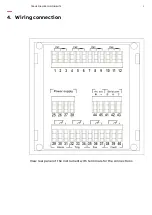
2.3 Connection of the temperature sensors
For the connection of the sensor RTD PT100 it’s necessary to
follow the indication of the wiring diagram of this manual: pay
attention to not invert the position between the conductors with
red insulator and the conductor with white insulator. The probes
type PT100 with three wires use the third wire to compensate the
resistance of the conductors (max 20 Ω).
If the sensor has two wires (normally white and red) it’s necessary
to short-circuit the terminals with the red wire (1-2, 4-5, 7-8, 10-11).
To reduce the external noises, it’s necessary to use the following
indication for the wires:
• use probes with shielded wire connected at earth and wires
twisted
• separate the wires of the probes from wires of power supply
• use wires with section at least of 0,5 mm
2
• use wires with conductor with tin or silver-plated
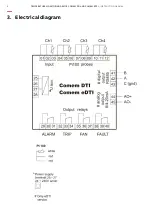
2.4 Output relays
For the connection of the output contacts it’s necessary to follow
the indication in the diagram.
The ALARM and TRIP relays commute when the threshold set
value gets over. The FAULT relay is normally energized, and it
commutes in presence of a PT100 anomaly or of the device.
During the normal functioning of the device the contact 38-39 is
open, while the 39-40 is closed.
The FAN relay is used to control the cooler fan, according to the
on/off thresholds set.