


LOAD/CUT
LOAD CURRENT TEST LOAD
HEATER
-5...5 V
1)
EXTRA INPUTS
EXTRA OUTPUT
1
2
3
4
5
6
7
8
9
10
11
12
13
14
15
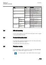
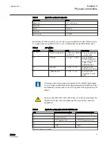
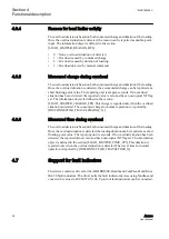
GUID-4A4FF16A-8E32-41CD-989E-AC0900D9C845 V2 EN
Figure 12:
X4 connector schematics
1)
Can be used as a 4...20 mA input using external resistor
3.2.6
I/O LEDs
The device has two LEDs indicating the AC and LINK status. Nine LEDs are
available to indicate the disconnector status. For indicating the grounding
disconnector status, the device has six LEDs.
3.2.6.1
AC and LINK LEDs
The device has two LEDs indicating the AC and LINK status.
Table 18:
AC and LINK LEDs
LED
Description
AC
AC power is connected to connector X2.1 pins 1 and 2
LINK
The IEC control link to SCADA is active
3.2.6.2
Disconnector LEDs
The device has nine LEDs to indicate the disconnector status. They are located on the
device front panel. Each disconnector has three LEDs, which indicate the status of the
disconnector.
Table 19:
Disconnector LEDs
Disconnector LED
Description
Disconnector 1 open
Disconnector 1 is opened
Disconnector 1 close
Disconnector 1 is closed
Disconnector 1 remote
Disconnector 1 is on remote control
Disconnector 2 open
Disconnector 2 is opened
Disconnector 2 close
Disconnector 2 is closed
Table continues on next page
Section 3
1MRS758459 C
Physical connections
24
ARC600
User Manual