


34
AO2000-LS25
LASER ANALYZERS | OI/AO2000-LS25-EN REV. D
7
Installation
Safety instructions
WARNING
Risk of injury due to process conditions.
The process conditions, for example high pressures and
temperatures, toxic and aggressive measuring media, can
give rise to hazards when working on the device.
• Before working on the device, make sure that the process
conditions do not pose any hazards.
• If necessary, wear suited personal protective equipment
when working on the device.
• Depressurize and empty the device / piping, allow to cool
and purge if necessary.
WARNING
Risk of injury due to live parts.
Improper work on the electrical connections can result in
electric shock.
• Connect the device only with the power supply switched
off.
• Observe the applicable standards and regulations for the
electrical connection.
Requirements for the installation site
To ensure optimum measuring operation, the following things
should be observed when choosing the measuring point or
installation site:
• The installation of the flanges or analyzer should be
carried out in one place with process pressure and
process temperature variations that are as low as
possible.
• The process gas flow should be as constant and
homogeneous as possible (e.g. no measurement directly
behind a line arc).
• The optical measuring path (optical path) should pass
through the center of the pipe.
• The dust concentration should be as low and
homogeneous as possible.
Flow conditions at measuring point
When deciding the placement of the analyzer in the process, we
recommend a minimum of 5 stack diameters of straight duct
before and 2 stack diameters of straight duct after the point of
measure.
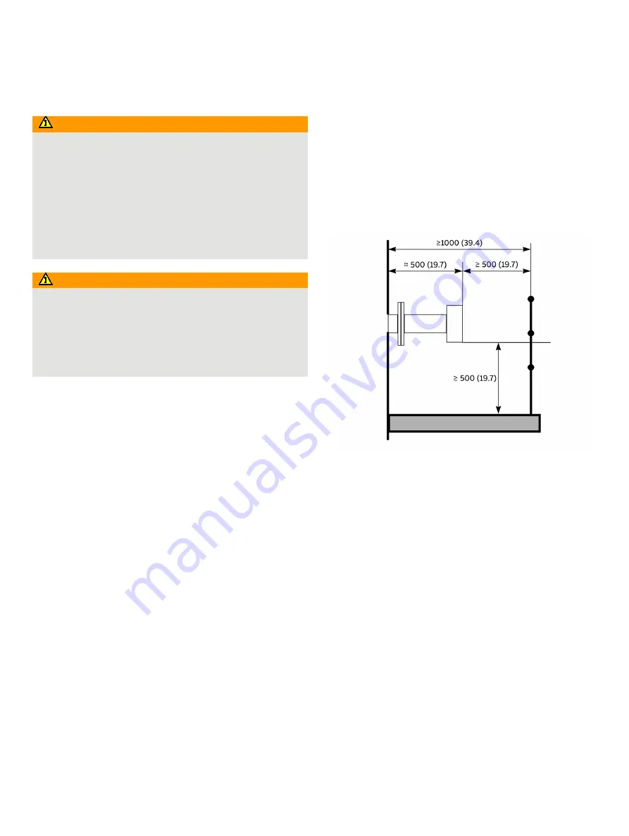
Installation of the measuring instrument
Both the transmitter and receiver units should be easily
accessible. A person should be able to stand in front of either the
transmitter unit or the receiver unit and adjust the M16 fixing
bolts using two standard spanners.
For the receiver unit there should be at least 1 m free space
measured from the flange fixed to the stack and outwards.
Figure 16: Transmitter and receiver installation tolerances
Flanges and stack hole requirements
The monitor requires two holes diametrically opposite to each
other, at least 50 mm in diameter.
Standard flanges used for connection are e.g. of type
DN 50 / PN 10 with an inner diameter of 50 mm and an outer
diameter of 165 mm.
The flanges can either be welded directly to the process or
optionally be part of a valve that is connected to the process for
safety reasons. The two alternatives are illustrated in
Figure 17
.


