background image

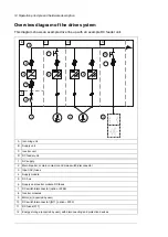
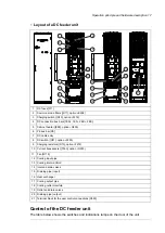
Layout of a DC feeder unit

1

8

9

10

11

12

16

17

18

19

20

21

13

14

15

2

3

4

5

6

7

DC fuses [F11]

1

Common mode filters ([R11], E208)

2

Charging switch ([Q10], F272)

3

DC connection bus bars [1ES+, 1ES-, 2ES+, 2ES-]

4

Cabinet heater ([E95], G300)

5

PE bus bar [PE]

6

DC cable entry

7

DC switch ([Q11], F290)

8

Charging resistors ([R10], F272)

9

Current transducers ([T353], G353)

10

Fan [G115]

11

Cooling input pipe

12

Cooling inlet manifold

13

Inlet and drain valves

14

Draining pipe (input)

15

Heat exchanger

16

Cooling output pipe

17

Cooling outlet manifold

18

Outlet and drain valves

19

Draining pipe (output)

20

Terminal block for the user control connections [X350]

21

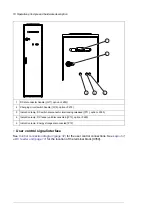
Control of the DC feeder unit

The table below shows the switches and indications lamps on the door of the unit.

Operation principle and hardware description 17

Содержание ACS880-7107LC DC

Страница 1: ... ABB INDUSTRIAL DRIVES ACS880 7107LC DC feeder unit Hardware manual ...

Страница 2: ......

Страница 3: ...ACS880 7107LC DC feeder unit Hardware manual Table of contents 4 Electrical installation 6 Start up 3AXD50000752423 Rev A EN Original instructions EFFECTIVE 2021 07 09 ...

Страница 4: ......

Страница 5: ...ignation label of the DC feeder unit 20 Type designation key 20 Basic code 20 Option codes 3 Guidelines for planning the electrical installation 23 Contents of this chapter 23 Limitation of liability 23 Generic guidelines 24 Selecting the energy storage 24 Implementing protections for the energy storage 24 General principles 25 Selecting the protective circuit breaker of the energy storage 25 Ener...

Страница 6: ...11 option F290 and without charging switch Q10 no option F272 41 Connecting the energy storage DC feeder unit with DC switch disconnector Q11 option F290 and charging switch Q10 option F272 42 Disconnecting the energy storage from the drive 42 Disconnecting the energy storage DC feeder without DC switch disconnector Q11 no option F290 42 Disconnecting the energy storage DC feeder unit with the DC ...

Страница 7: ...er cables 56 Tightening torques 56 Electrical connections 56 Mechanical connections 56 Insulation supports 56 Cable lugs 56 Typical power cables 57 Terminal X350 data for the control cables 57 DC connection data 57 Auxiliary circuit current consumption 57 Energy efficiency data ecodesign 57 Protection classes 57 Ambient conditions 58 Materials 58 Color 59 Package 59 Disposal 59 Applicable standard...

Страница 8: ...8 ...

Страница 9: ...ware function specific warnings and notes before changing the default settings of a function For each function the warnings and notes are given in the section describing the related user adjustable parameters Read the task specific safety instructions before starting the task See the section describing the task Target audience This manual is intended for people who plan the installation install st...

Страница 10: ...y module s under control of one control unit and related components Supply unit Related documents Code Manual General manuals 3AXD50000048633 ACS880 liquid cooled multidrive cabinets and modules safety instructions 3AXD50000048634 ACS880 liquid cooled multidrive cabinets and modules electrical planning instructions 3AXD50000048635 ACS880 liquid cooled multidrive cabinets mechanical installation in...

Страница 11: ... supplement 3AUA0000085685 ACS AP x assistant control panels user s manual 3AUA0000094606 Drive composer start up and maintenance PC tool user s manual 3AXD50000210268 Converter module lifting device for drive cabinets hardware manual Manuals for I O extension modules fieldbus adapters safety options etc You can find manuals on the Internet See www abb com drives documents For manuals not availabl...

Страница 12: ...12 ...

Страница 13: ...r super capacitor The energy storage media does not belong to the DC feeder unit product offering One DC feeder unit can contain one single or up to 3 parallel connected strings Parallel strings must be connected to separate energy storages Each parallel string must also have its own connection cabling For more information contact ABB Typically the DC feeder unit is used in marine applications for...

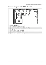
Страница 14: ... supply 1 Main breaker or main contactor and main switch disconnector 2 Input AC fuses 3 Supply module 4 DC bus 5 Supply and inverter module DC fuses 6 DC switch disconnector option F286 7 Inverter modules 8 Motor s acquired by user 9 DC switch disconnector Q11 option F290 10 DC fuses F11 11 Energy storage acquired by user with disconnecting and protection devices 12 14 Operation principle and har...

Страница 15: ...d 1 DC switch disconnector Q11 option F290 2 Charging circuit switch Q10 resistors R10 option F272 3 DC fuses F11 4 Common mode filters R11 option E208 5 Current transducers T353 option G353 6 External DC connection terminals ES ES 7 Operation principle and hardware description 15 ...

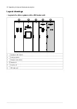
Страница 16: ...out of a drive system with a DC feeder unit 1 2 3 4 5 Auxiliary control cubicle 1 Incoming cubicle 2 Supply module cubicle 3 Supply unit 1 3 Inverter unit 4 DC feeder unit 5 16 Operation principle and hardware description ...

Страница 17: ...g resistors R10 option F272 9 Current transducers T353 option G353 10 Fan G115 11 Cooling input pipe 12 Cooling inlet manifold 13 Inlet and drain valves 14 Draining pipe input 15 Heat exchanger 16 Cooling output pipe 17 Cooling outlet manifold 18 Outlet and drain valves 19 Draining pipe output 20 Terminal block for the user control connections X350 21 Control of the DC feeder unit The table below ...

Страница 18: ...P11 option F290 3 Indication lamp DC feeder unit disconnected P13 option F290 4 Indication lamp Energy storage disconnected P12 5 User control signal interface See Control connection diagram page 32 for the user control connections See Layout of a DC feeder unit page 17 for the location of the terminal block X350 18 Operation principle and hardware description ...

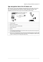
Страница 19: ...C 950 A 1190403889 Output MADE IN FINLAND 1xST FRAME IP42 Liquid cooling 1 2 3 4 5 6 7 Type designation 1 Number or parallel strings 2 Cooling system and other additional data 3 Degree of protection 4 Ratings 5 Valid markings See ACS880 liquid cooled multidrive cabinets and modules electrical planning instruc tions 3AXD50000048634 English 6 Serial number The first digit of the serial number refers...

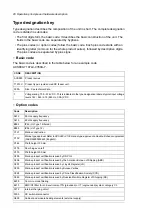
Страница 20: ...n codes Description Code 50 Hz supply frequency A012 60 Hz supply frequency A013 IP42 UL Type 1 Filtered B054 IP54 UL Type 12 B055 Marine construction C121 Marine type approval Refer to ACS880 C132 marine type approved cabinet built drives supplement 3AXD50000039629 English C132 Plinth height 100 mm C164 Door hinges on left C176 Plinth height 200 mm C179 Marine product certification issued by DNV ...

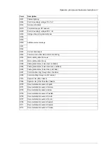
Страница 21: ...Cable gland plates 3 mm aluminum undrilled H364 Cable gland plates 6 mm brass undrilled H365 Control cable entry through floor of cabinet H367 Control cabling through roof of cabinet H368 Special color RAL Classic P913 Special color other than RAL Classic P966 Documentation manuals in English R700 Documentation manuals in German R701 Documentation manuals in Italian R702 Documentation manuals in S...

Страница 22: ...22 ...

Страница 23: ...tion which breaches the local laws and or other regulations Furthermore if the recommendations given by ABB are not followed the drive may experience problems that the warranty does not cover Generic guidelines See ACS880 liquid cooled multidrive cabinets and modules electrical planning instructions 3AXD50000048634 English for the generic guidelines for planning the electrical installation selecti...

Страница 24: ...it parameter group 123 DC volt ref where UDC Drive DC voltage in the DC bus UAC Drive input voltage AC ABB recommends to measure the energy storage voltage If the energy storage is a super capacitor voltage measurement is obligatory unless the capacitor withstands the maximum DC voltage of the drive or contains internal overvoltage protection Equip the energy storage with a circuit breaker capable...

Страница 25: ...with an disconnecting device The disconnecting device does not belong to the drive delivery Protecting the energy storage cable ABB equips the DC feeder unit with fuses as standard The fuses protect the unit and cables in a cable short circuit situation The customer or the system integrator must equip the energy storage with overload and short circuit protection for the cable Energy storage discha...

Страница 26: ... core cable can only be used if it is routed inside a cabinet that efficiently suppresses radiated emissions Install the cables away from other cable routes Avoid long parallel runs with other cables The minimum parallel cabling separation distance should be 0 3 meters Cross other cables at right angles Keep the cable as short as possible in order to minimize the radiated emissions Maximum cable l...

Страница 27: ...ical installation Contents of this chapter Electrical safety precautions These electrical safety precautions are for all personnel who do work on the drive motor cable or motor 4 Electrical installation 27 11 ...

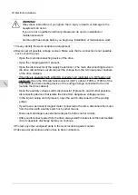
Страница 28: ...nit optional or a DC feeder unit optional Open the DC switch disconnector Q11 option F286 or F290 of the unit Open the disconnecting device of the energy storage connected to the unit outside the drive cabinet Open the auxiliary voltage switch disconnector if present and all other possible disconnecting devices that isolate the drive from dangerous voltage sources In the liquid cooling unit if pre...

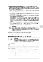
Страница 29: ...ding PE terminal is zero In cabinet built drives measure between the drive DC busbars and and the grounding PE busbar WARNING The busbars inside the cabinet of liquid cooled drives are partially coated Measurements made through the coating are potentially unreliable so only measure at uncoated portions Note that the coating does not constitute a safe or touch proof insulation 6 Install temporary g...

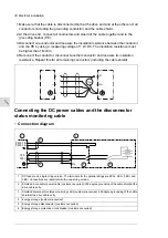
Страница 30: ...remaining conductors including the cable shield Ohm ES ES Connecting the DC power cables and the disconnector status monitoring cable Connection diagram 1ES 1ES X350 16 X350 14 1 3 2 4 5 6 DC feeder unit single string version The terminals for the parallel strings are 2ES 2ES 3ES and 3ES Connections are identical with the one string version 1 Shielded 4 conductor power cable customer acquired 360 ...

Страница 31: ... the cable and conductor ends and install the cable lugs at the end of the conductors Use bolt M12 for the DC busbar connection and M10 for the PE busbar connection 6 Connect the conductors to appropriate terminals Tighten to 70 N m Note The image below shows the connection for a two string version of the unit See the delivery specific circuit diagrams for the number of strings and actual connecti...

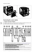
Страница 32: ... 11 12 Terminal block for the control connections For the location see Layout of a DC feeder unit page 17 X350 Unit with a common mode filter R11 11 R11 12 F45 option E208 Overtemperature relay K45 Unit with charging switch Q10 option F272 Charging switch Q10 1 Unit with DC switch disconnector Q11 option F290 DC switch disconnector Q11 1 Unit with DC switch disconnector Q11 option F290 Indicator l...

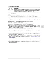
Страница 33: ...option F272 Q10 status indication Closed contact Q10 is open Optional user connection is not shown 11 Unit equipped with a common mode filter R11 11 R11 12 F45 option E208 Overtemperature in dication of filter Optional user connection is not shown in the diagram 12 Connection procedure WARNING Obey the safety instructions of the drive If you ignore them injury or death or damage to the equipment c...

Страница 34: ...hten the two tightening screws so that the EMI conductive cushions press tightly round the bare shield 5 Attach the cable with a cable tie to the support above the cushions 1 2 4 3 34 Electrical installation ...

Страница 35: ...ure that the switch is turned to open position and locked The energy storage cable has been connected to the correct terminals drive and energy storage and the terminals have been tightened to the torque specified There is an adequately sized protective earth ground conductor between the energy storage and the drive the conductor has been connected to the appropriate terminal and the terminal has ...

Страница 36: ...36 ...

Страница 37: ...ot be connected to drive inadvertently Make sure that all external auxiliary circuits are switched off and disconnected See the start up instruc tions in the supply unit hardware manual Make sure that the supply unit is switched off and the drive system has been isolated from the supply network DC feeder unit with the DC switch disconnector Q11 option F290 Make sure that the DC switch disconnector...

Страница 38: ...bicles Closing the cabinet doors Close all cabinet doors Connecting voltage to the drive and its auxiliary circuits Connect main AC voltage to the input terminals of the drive supply unit Close the main breaker of the supply transformer Close the main disconnecting device of the drive Rack in the main breaker Q1 option F255 or close the main switch disconnector option F253 Close the auxiliary volt...

Страница 39: ... want to prevent this for any of the units open its DC switch discon nector if available or remove its DC fuses 1 Make sure that DC switch disconnector Q11 and charging switch Q10 are open Indicator P13 is on 2 Make sure that the energy storage disconnector is open Indicator P12 is on 3 Start the drive supply unit and energize the drive Use operating switch S21 on the door of the drive incoming cu...

Страница 40: ...40 ...

Страница 41: ...ve and DC feeder unit DC feeder unit without DC switch disconnector Q11 no option F290 page 38 Connecting the energy storage DC feeder unit with the DC switch disconnector Q11 option F290 and without charging switch Q10 no option F272 See Energizing the drive and DC feeder unit DC feeder unit with DC switch disconnector Q11 option F290 and without charging switch Q10 no option F272 page 38 Connect...

Страница 42: ...terlocking Indicator P11 is on 4 Open the DC switch disconnector Q11 Indicator P13 goes on 5 If necessary lock and tag DC switch disconnector Q11 and the energy storage disconnector The energy storage has been disconnected from the drive DC link Disconnecting the energy storage DC feeder unit with DC switch disconnector Q11 option F290 and charging switch Q10 option F272 1 Open the energy storage ...

Страница 43: ...or Description when illuminated Name Desig DC switch disconnector Q11 option F290 is released Interlocking released P11 Energy storage disconnector is open ESS disconnected P12 The DC switch disconnector Q11 option F290 is disconnected and the charging switch Q10 option F272 is disconnected DC feeder disconnec ted P13 8 Fault tracing 43 ...

Страница 44: ...44 ...

Страница 45: ...rmation consult your local ABB Service representative www abb com searchchannels Description of symbols Description Action Inspection visual inspection and maintenance action if needed I Performance of on off site work commissioning tests measurements or other P work Replacement R Recommended maintenance intervals after start up Recommended annual actions by the user Connections and environment P ...

Страница 46: ...s to ensure the highest reliability and optimum performance Long term operation near the specified maximum ratings or ambient conditions may require shorter maintenance intervals for certain components Consult your local ABB Service representative for additional maintenance recommendations Cabinet Cleaning the exterior of the drive WARNING Obey the safety instructions of the drive If you ignore th...

Страница 47: ... do installation or maintenance work 1 Stop the drive and do the steps in section Electrical safety precautions page 27 before you start the work 2 Examine the tightness of the cable connections Use the tightening torques given in the technical data Fans Replacing the cooling fan of the heat exchanger WARNING Obey the safety instructions of the drive If you ignore them injury or death or damage to...

Страница 48: ...eves Some parts have sharp edges 1 Stop the drive and do the steps in section Electrical safety precautions page 27 before you start the work 2 Undo the fastening screws 2 x M6 and open the swing out frame 3 Remove the shrouding in front of the fan 4 Disconnect the fan wiring 48 Maintenance ...

Страница 49: ...5 Undo the fastening screws and pull the fan housing up and out 6 Install a new fan in reverse order to the above Fuses Replacing the fuses To be added Maintenance 49 ...

Страница 50: ...50 ...

Страница 51: ...Internal cooling circuit See ACS880 107LC inverter units hardware manual 3AXD50000196111 English 10 Internal cooling circuit 51 ...

Страница 52: ...52 ...

Страница 53: ...540 436 360 1 ST 0350A 7 354 363 454 466 478 473 727 600 485 400 1 ST 0550A 7 398 408 511 524 538 532 818 680 546 450 1 ST 0750A 7 425 435 545 559 574 568 873 720 582 480 1 ST 0950A 7 496 508 636 652 669 663 1018 840 679 560 2 ST 1100A 7 549 562 704 722 741 734 1128 930 752 620 2 ST 1500A 7 620 635 795 815 837 828 1273 1050 849 700 2 ST 1900A 7 681 698 875 896 920 911 1400 1160 934 770 3 ST 1650A ...

Страница 54: ...M6549 Bussmann 1000 1100 6 2250A 7 170M6501 Bussmann 1100 1400 6 2850A 7 1 Fuses are also UL Recognized Dimensions and weights Weight Depth Width Space above Height ACS880 7107LC kg mm mm mm mm Un 690 V TBD 644 400 250 2002 0350A 7 TBD 644 400 250 2002 0550A 7 TBD 644 400 250 2002 0750A 7 TBD 644 400 250 2002 0950A 7 TBD 644 500 250 2002 1100A 7 TBD 644 500 250 2002 1500A 7 TBD 644 500 250 2002 19...

Страница 55: ...Terminal and cable entry data for the power cables Technical data 55 ...

Страница 56: ...m 7 4 lbf ft M6 8 8 24 N m 17 7 lbf ft M8 Insulation supports Strength class Max torque Size 8 8 5 N m 44 lbf in M6 8 8 9 N m 6 6 lbf ft M8 8 8 18 N m 13 3 lbf ft M10 8 8 31 N m 23 lbf ft M12 Cable lugs Strength class Max torque Size 8 8 15 N m 11 lbf ft M8 8 8 32 N m 23 5 lbf ft M10 8 8 50 N m 37 lbf ft M12 Typical power cables Example cable types in marine applications Prysmian TEMA PHFX A LSM H...

Страница 57: ... scope of the EU ecodesign requirements Regulation EU 2019 1781 or the UK ecodesign requirements Regulation SI 2021 No 745 Protection classes IP42 standard IP54 option B055 Degrees of protection IEC EN 60529 UL Type 1 standard UL Type 12 option B055 For indoor use only Enclosure types UL50 III except for auxiliary power connections fan control heating lighting cooling unit pump etc which are categ...

Страница 58: ...king must support this otherwise 1S2 Chemical gases Class 3C2 Solid particles Class 3S2 No conductive dust al lowed 2 Pollution degree IEC EN 60721 3 2 1997 IEC EN 60721 3 1 1997 IEC EN 60721 3 3 2002 Vibration 2 9 Hz max 3 5 mm amplitude 10 57 Hz max 0 075 mm amplitude 10 57 Hz max 0 075 mm amplitude IEC EN 61800 5 1 IEC 60068 2 6 2007 EN 60068 2 6 2008 Envir onmental testing Part 2 Tests Test Fc...

Страница 59: ...als can be recycled as material Plastics rubber cardboard and other packaging material can be used in energy recovery Printed circuit boards and large electrolytic capacitors need selective treatment according to IEC 62635 guidelines To aid recycling plastic parts are marked with an appropriate identification code Contact your local ABB distributor for further information on environmental aspects ...

Страница 60: ... establish and maintain any appropriate measures such as but not limited to the installation of firewalls prevention of physical access application of authentication measures encryption of data installation of anti virus programs etc to protect the product the network its system and the interface against any kind of security breaches unauthorized access interference intrusion leakage and or theft ...

Страница 61: ... by navigating to www abb com searchchannels Product training For information on ABB product training navigate to new abb com service training Providing feedback on ABB manuals Your comments on our manuals are welcome Navigate to new abb com drives manuals feedback form Document library on the Internet You can find manuals and other product documents in PDF format on the Internet at www abb com dr...

Страница 62: ...www abb com drives 3AXD50000752423A Copyright 2021 ABB All rights reserved Specifications subject to change without notice 3AXD50000752423 Rev A EN EFFECTIVE 2021 07 09 ...

Отзывы: