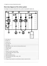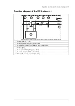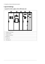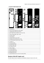
Overview diagram of the drive system
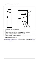
This diagram shows an example drive line up with an example DC feeder unit.
1
3
4
6
5
8
8
12
9
7
2
A
B
C
C
D
11
10
Incoming unit
A
Supply unit
B
Inverter unit
C
DC feeder unit
D
AC supply
1
Main breaker, or main contactor and main switch-disconnector
2
Input (AC) fuses
3
Supply module
4
DC bus
5
Supply and inverter module DC fuses
6
DC switch/disconnector (F286)
7
Inverter modules
8
Motor(s) (acquired by user)
9
DC switch/disconnector ([Q11], F290)
10
DC fuses [F11]
11
Energy storage (acquired by user) with disconnecting and protection devices
12
14 Operation principle and hardware description
Содержание ACS880-7107LC DC
Страница 1: ... ABB INDUSTRIAL DRIVES ACS880 7107LC DC feeder unit Hardware manual ...
Страница 2: ......
Страница 4: ......
Страница 8: ...8 ...
Страница 12: ...12 ...
Страница 22: ...22 ...
Страница 36: ...36 ...
Страница 40: ...40 ...
Страница 44: ...44 ...
Страница 50: ...50 ...
Страница 52: ...52 ...
Страница 55: ...Terminal and cable entry data for the power cables Technical data 55 ...


