


WARNING!
The Safe torque off function does not disconnect the voltage of the main and
auxiliary circuits from the drive. Therefore maintenance work on electrical parts of
the drive or the motor can only be carried out after isolating the drive from the main
supply.
WARNING!
The Safe torque off functionality is only achieved through the XSTO connector of
the inverter control unit (A41). True Safe torque off functionality is not achieved
through the XSTO connectors of other control units (such as the supply control
unit or the brake control unit).
The Safe torque off function is supported by the ACS880 inverter control program. It is not
supported by supply or brake firmware.
WARNING!
(With permanent magnet or synchronous reluctance [SynRM] motors only) In case
of a multiple IGBT power semiconductor failure, the inverter system can produce
an alignment torque which maximally rotates the motor shaft by 180/
p
(with
permanent magnet motors) or 180/2
p
(with synchronous reluctance [SynRM]
motors) degrees regardless of the activation of the Safe torque off function.
p
denotes the number of pole pairs.
Notes:
•
If a running drive is stopped by using the Safe torque off function, the drive will cut off
the motor supply voltage and the motor will coast to a stop. If this causes danger or is
not otherwise acceptable, stop the drive and machinery using the appropriate stop mode
before activating the Safe torque off function.
•
The Safe torque off function overrides all other functions of the inverter unit.
•
The Safe torque off function is ineffective against deliberate sabotage or misuse.
•
The Safe torque off function has been designed to reduce the recognized hazardous
conditions. In spite of this, it is not always possible to eliminate all potential hazards.
The assembler of the machine must inform the final user about the residual risks.
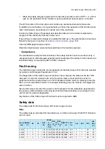
Maintenance
After the operation of the circuit is validated at start-up, the STO function shall be maintained
by periodic proof testing. In high demand mode of operation, the maximum proof test interval
is 20 years. In low demand mode of operation, the maximum proof test interval is 5 or 2
years; see section
. It is assumed that all dangerous failures of the
STO circuit are detected by the proof test. To perform the proof test, do the
.
Note:
See also the Recommendation of Use CNB/M/11.050 (published by the European
co-ordination of Notified Bodies) concerning dual-channel safety-related systems with
electromechanical outputs:
•
When the safety integrity requirement for the safety function is SIL 3 or PL e (cat. 3 or
4), the proof test for the function must be performed at least every month.
260 The Safe torque off function
Содержание ACS880-07
Страница 1: ...ABB industrial drives Hardware manual ACS880 07 drives 560 to 2800 kW ...
Страница 2: ......
Страница 4: ......
Страница 22: ...22 ...
Страница 28: ...28 ...
Страница 94: ...94 ...
Страница 112: ...Electrical installation 109 5 6 4 3 112 Electrical installation ...
Страница 113: ...110 Electrical installation 7 8 8 Electrical installation 113 ...
Страница 114: ...Electrical installation 111 9 10 114 Electrical installation ...
Страница 116: ...Electrical installation 113 4 5 3 6 7 116 Electrical installation ...
Страница 118: ...2 11 b PE 10 7 5 6 8 a 360 grounding detail 118 Electrical installation ...
Страница 128: ...128 ...
Страница 146: ...146 ...
Страница 148: ...148 ...
Страница 159: ...12 Install and tighten the two M4 12 T20 screws 10 11 12 Maintenance 159 ...
Страница 162: ...6 6a 6a 6b 7a 7b 7 8 8a 8b 162 Maintenance ...
Страница 166: ...166 Maintenance 6 6 7 8 7 166 Maintenance ...
Страница 173: ...6 Reinstall the cover removed earlier and close the cubicle door 4 4 D7T D8T Maintenance 173 ...
Страница 213: ... Dimension drawing examples Frame 2 D7T 2 R8i 12 pulse A004 Dimensions 213 ...
Страница 214: ...Frame 1 D8T 2 R8i IP22 214 Dimensions ...
Страница 215: ...Frame 1 D8T 2 R8i IP54 B055 Dimensions 215 ...
Страница 216: ...Frame 1 D8T 2 R8i with common motor terminal cubicle H359 1 2 216 Dimensions ...
Страница 217: ...Frame 1 D8T 2 R8i with common motor terminal cubicle H359 2 2 Dimensions 217 ...
Страница 218: ...Frame 1 D8T 2 R8i with brake choppers and resistors D150 D151 1 2 218 Dimensions ...
Страница 219: ...Frame 1 D8T 2 R8i with brake choppers and resistors D150 D151 2 2 Dimensions 219 ...
Страница 220: ...Frame 1 D8T 2 R8i with sine output filter E206 1 2 220 Dimensions ...
Страница 221: ...Frame 1 D8T 2 R8i with sine output filter E206 2 2 Dimensions 221 ...
Страница 222: ...Frame 2 D8T 2 R8i 12 pulse A004 with grounding switch F259 222 Dimensions ...
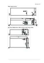
Страница 223: ...Frame 2 D8T 3 R8i 1 2 Dimensions 223 ...
Страница 224: ...Frame 2 D8T 3 R8i 2 2 224 Dimensions ...
Страница 225: ...Frame 2 D8T 3 R8i with common motor terminal cubicle H359 1 2 Dimensions 225 ...
Страница 226: ...Frame 2 D8T 3 R8i with common motor terminal cubicle H359 2 2 226 Dimensions ...
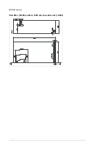
Страница 227: ...Frame 2 D8T 3 R8i with top entry top exit H351 H353 1 2 Dimensions 227 ...
Страница 228: ...Frame 2 D8T 3 R8i with top entry top exit 2 2 228 Dimensions ...
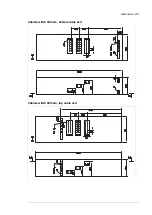
Страница 229: ...Frame 3 D8T 4 R8i 1 2 Dimensions 229 ...
Страница 230: ...Frame 3 D8T 4 R8i 2 2 230 Dimensions ...
Страница 231: ...Frame 3 D8T 4 R8i with common motor terminal cubicle H359 1 2 Dimensions 231 ...
Страница 232: ...Frame 3 D8T 4 R8i with common motor terminal cubicle H359 2 2 232 Dimensions ...
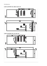
Страница 233: ...Frame 3 D8T 4 R8i with top entry top exit H351 H353 1 2 Dimensions 233 ...
Страница 234: ...Frame 3 D8T 4 R8i with top entry top exit H351 H353 2 2 234 Dimensions ...
Страница 235: ...Frame 4 D8T 5 R8i 6 pulse with top entry exit UL Listed C129 1 2 Dimensions 235 ...
Страница 236: ...Frame 4 D8T 5 R8i 6 pulse with top entry exit UL Listed C129 2 2 236 Dimensions ...
Страница 237: ... Dimensions of empty cubicles options C199 C200 C201 IP22 IP42 Dimensions 237 ...
Страница 238: ...IP54 238 Dimensions ...
Страница 242: ... 600 mm with main breaker bottom cable entry 600 mm with main breaker top cable entry 242 Dimensions ...
Страница 243: ... 1000 mm UL CSA top cable entry Dimensions 243 ...
Страница 244: ... 1000 mm UL CSA bottom cable entry 244 Dimensions ...
Страница 264: ...264 ...
Страница 272: ... 272 ...
Страница 274: ...Contact us www abb com drives www abb com drivespartners 3AUA0000143261 E EN EFFECTIVE 2017 06 05 3AUA0000143261E ...


