


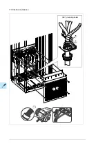


8.
Attach the conductive sleeves to the cable shields with cable ties. Tie up the unused
conductive sleeves with cable ties.
9.
Seal the slot between the cable and mineral wool sheet (if used) with sealing compound
(eg. CSD-F, ABB brand name DXXT-11, code 35080082).
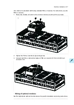
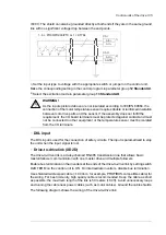
10. Connect the twisted shields of the cables to the PE busbar of the cabinet.
11. Connect the phase conductors of the input cable to the L1, L2 and L3 terminals. (With
12-pulse connection, the terminals are 1L1, 1L2 and 1L3 for one 6-pulse supply line,
2L1, 2L2 and 2L3 for the other.) Tighten the screws to the torque given under
12. Reinstall the shrouding removed earlier.
13. Close the cubicle door.
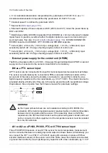
Connecting a PC
A PC (with eg. the Drive composer PC tool) can be connected to the inverter unit as follows:
1.
Connect an ACS-AP-I control panel to the inverter control unit either by using an Ethernet
(eg. CAT5E) networking cable, or by inserting the panel into the panel holder (if present).
WARNING!
Do not connect the PC directly to the control panel connector of the inverter
unit as this can cause damage.
2.
Remove the USB connector cover on the front of the control panel.
3.
Connect an USB cable (Type A to Type Mini-B) between the USB connector on the
control panel (3a) and a free USB port on the PC (3b).
4.
The panel will display an indication whenever the connection is active.
124 Electrical installation
Содержание ACS880-07
Страница 1: ...ABB industrial drives Hardware manual ACS880 07 drives 560 to 2800 kW ...
Страница 2: ......
Страница 4: ......
Страница 22: ...22 ...
Страница 28: ...28 ...
Страница 94: ...94 ...
Страница 112: ...Electrical installation 109 5 6 4 3 112 Electrical installation ...
Страница 113: ...110 Electrical installation 7 8 8 Electrical installation 113 ...
Страница 114: ...Electrical installation 111 9 10 114 Electrical installation ...
Страница 116: ...Electrical installation 113 4 5 3 6 7 116 Electrical installation ...
Страница 118: ...2 11 b PE 10 7 5 6 8 a 360 grounding detail 118 Electrical installation ...
Страница 128: ...128 ...
Страница 146: ...146 ...
Страница 148: ...148 ...
Страница 159: ...12 Install and tighten the two M4 12 T20 screws 10 11 12 Maintenance 159 ...
Страница 162: ...6 6a 6a 6b 7a 7b 7 8 8a 8b 162 Maintenance ...
Страница 166: ...166 Maintenance 6 6 7 8 7 166 Maintenance ...
Страница 173: ...6 Reinstall the cover removed earlier and close the cubicle door 4 4 D7T D8T Maintenance 173 ...
Страница 213: ... Dimension drawing examples Frame 2 D7T 2 R8i 12 pulse A004 Dimensions 213 ...
Страница 214: ...Frame 1 D8T 2 R8i IP22 214 Dimensions ...
Страница 215: ...Frame 1 D8T 2 R8i IP54 B055 Dimensions 215 ...
Страница 216: ...Frame 1 D8T 2 R8i with common motor terminal cubicle H359 1 2 216 Dimensions ...
Страница 217: ...Frame 1 D8T 2 R8i with common motor terminal cubicle H359 2 2 Dimensions 217 ...
Страница 218: ...Frame 1 D8T 2 R8i with brake choppers and resistors D150 D151 1 2 218 Dimensions ...
Страница 219: ...Frame 1 D8T 2 R8i with brake choppers and resistors D150 D151 2 2 Dimensions 219 ...
Страница 220: ...Frame 1 D8T 2 R8i with sine output filter E206 1 2 220 Dimensions ...
Страница 221: ...Frame 1 D8T 2 R8i with sine output filter E206 2 2 Dimensions 221 ...
Страница 222: ...Frame 2 D8T 2 R8i 12 pulse A004 with grounding switch F259 222 Dimensions ...
Страница 223: ...Frame 2 D8T 3 R8i 1 2 Dimensions 223 ...
Страница 224: ...Frame 2 D8T 3 R8i 2 2 224 Dimensions ...
Страница 225: ...Frame 2 D8T 3 R8i with common motor terminal cubicle H359 1 2 Dimensions 225 ...
Страница 226: ...Frame 2 D8T 3 R8i with common motor terminal cubicle H359 2 2 226 Dimensions ...
Страница 227: ...Frame 2 D8T 3 R8i with top entry top exit H351 H353 1 2 Dimensions 227 ...
Страница 228: ...Frame 2 D8T 3 R8i with top entry top exit 2 2 228 Dimensions ...
Страница 229: ...Frame 3 D8T 4 R8i 1 2 Dimensions 229 ...
Страница 230: ...Frame 3 D8T 4 R8i 2 2 230 Dimensions ...
Страница 231: ...Frame 3 D8T 4 R8i with common motor terminal cubicle H359 1 2 Dimensions 231 ...
Страница 232: ...Frame 3 D8T 4 R8i with common motor terminal cubicle H359 2 2 232 Dimensions ...
Страница 233: ...Frame 3 D8T 4 R8i with top entry top exit H351 H353 1 2 Dimensions 233 ...
Страница 234: ...Frame 3 D8T 4 R8i with top entry top exit H351 H353 2 2 234 Dimensions ...
Страница 235: ...Frame 4 D8T 5 R8i 6 pulse with top entry exit UL Listed C129 1 2 Dimensions 235 ...
Страница 236: ...Frame 4 D8T 5 R8i 6 pulse with top entry exit UL Listed C129 2 2 236 Dimensions ...
Страница 237: ... Dimensions of empty cubicles options C199 C200 C201 IP22 IP42 Dimensions 237 ...
Страница 238: ...IP54 238 Dimensions ...
Страница 242: ... 600 mm with main breaker bottom cable entry 600 mm with main breaker top cable entry 242 Dimensions ...
Страница 243: ... 1000 mm UL CSA top cable entry Dimensions 243 ...
Страница 244: ... 1000 mm UL CSA bottom cable entry 244 Dimensions ...
Страница 264: ...264 ...
Страница 272: ... 272 ...
Страница 274: ...Contact us www abb com drives www abb com drivespartners 3AUA0000143261 E EN EFFECTIVE 2017 06 05 3AUA0000143261E ...


