Page 34
© Copyright 2021 ABB. All rights reserved.
NOTE:
In the following steps, closing a CB1 circuit breakers (up position) will energize the loads
connected to the plant, further, in multiple
-
shelf systems the AC output from any shelf will
feed back to the AC output terminal blocks on all shelves.
CAUTION:
In a multiple shelf system, never close a shelf CB1 when the shelf is DC powered unless
there is a functioning System Controller in the shelf and the shelf
’
s inverters are indicating
STANBY mode (amber LEDs ON).
10.Assure that all inverters on all shelves are indicating standby mode
-
all STANDBY LEDs
-
ON.
11.Turn ON CB1 circuit breakers of all shelves.
12.Observe the Controller goes through the System Update process for all the modules on its shelf and the
inverter OK LEDs all turn ON.
13.Observe that
•
Each Inverter green OK LEDs is ON
•
Each Distribution Module green OK LEDs are ON,
•
Each System Controller red INVERTER MAJOR LED is OFF, and
•
Each System Controller green LED is ON.
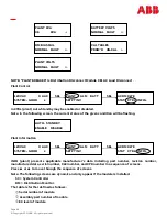
14.If no alarms are present, the displays will appear as follows:
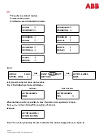
15.The system displays will appear as follows if there are any alarm conditions:
16.Pressing the SEL key will take the user to the main menu displayed as follows. From the main menu, the user
can review the plant status or make system changes.
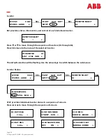
17.The active selection will be flashing. The user can press SEL to select the active selection, or may scroll to the
next selection by the use of the arrow keys. Pressing the BACK key will take the user back to the System Status
Screen.
Refer to Display Navigation and Push Buttons and Display Menus sections.
XXX VAC X AAC
SYSTEM
-
GOOD s
120 VAC X AAC
SYSTEM
-
ALARM s
PLANT ALM BATT
SETPT INV s

