background image

A

Appendix

A-1

Dimensions

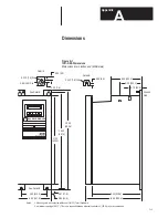
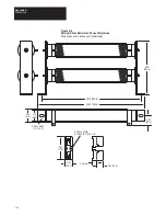
Figure A.1
1391-DES Dimensions 
Dimensions are in inches and (millimeters)

17.13

(435.1)

18.40

(467.4)

19.00

(482.6)

4.50 (114.3)

6.20 (157.5)

See Detail B

0.67 (17.0)

0.85 (21.6)

11.56 (293.6)

9.10 (228.6)

6.00 (152.4)

5.20 (132.1)

3.70 (93.9)

0.312 (7.9) Dia.

0.30 (7.6)

0.25 (6.3)

0.60 (15.2) Dia.

See Detail A

Detail A

Detail B

0.39 (9.9)

0.312 (7.9) Dia.

Notes:

1. Mounting slots and keyholes will accept 1/4–20 (7 mm) hardware.
2. A minimum spacing of 0.312” (7.9 mm) is required between adjacent controllers 1” (25.4 mm) is recommended.

Ground
Stud

1391

DIGITAL AC SERVO DRIVE

Status

Enable

ALLEN–BRADLEY

Содержание 1391-DES Series

Страница 1: ...epair services USA 1 888 932 9183 Canada 1 905 829 2505 Emergency After hours 1 416 624 0386 Servicing USA and Canada Scroll down to view your document Over 100 years cumulative experience 24 hour rush turnaround technical support service Established in 1993 The leading independent repairer of servo motors and drives in North America ...

Страница 2: ...User Manual 1391 DES Digital AC Servo Drive ...

Страница 3: ...bility or liability for actual use based upon the illustrative uses and applications No patent liability is assumed by Allen Bradley Company with respect to use of information circuits or equipment described in this text Reproduction of the content of this manual in whole or in part without written permission of the Allen Bradley Company is prohibited This information in this manual is organized i...

Страница 4: ...info 3 4 7 8 New Important statement added to TB1 5 1 New Bus voltage info added to shunt resistor 5 4 New Important statement added 5 7 Clarification Parameter 69 name change 6 14 Update Parameter 170 maximum value updated 6 18 Update Parameter 199 updated 6 20 Update Encoder Wiring 7 5 Clarification Torque Plus info added to step 11 8 3 New Torque Plus info added steps 30 31 8 7 New Figure 8 1 u...

Страница 5: ...cs and limitations of this equipment including hazards associated with installation programming and maintenance procedures Note the following points This equipment has been designed to meet the requirements of a component drive in an integrated drive system While the potential hazards associated with the drive remain the same when used in a system environment it must be noted that special consider...

Страница 6: ... may result if ESD control procedures are not followed If you are not familiar with static control procedures reference Allen Bradley publication 8000 4 5 2 Guarding Against Electrostatic Damage or any other applicable ESD Protection Handbook Certification Notice In order to maintain UL listing on Allen Bradley 1391 DES Digital Servo Drives the user must provide power from a 1391 Isolation Transfo...

Страница 7: ...e in ratings of 15 22 5 and 45A RMS with all package sizes being identical A 1391 Transformer 1326 AC Servomotor and 1326 Cables complete the servo system Standard Features The 1391 DES contains a number of standard features required in a typical automated machine servo system Input protected against transient voltage A power line DB contactor which opens the AC line to the drive and inserts a shu...

Страница 8: ...watts continuous can be supplied for user mounting on 22 5A drives This is selectable by removing the jumper on TB5 and using an external resistor The shunt has integral fusing accessible from the outside of 15 and 22 5A drives The 45A drive has an externally mounted resistor and fuse Important An external shunt regulator resistor is included as standard equipment on 45A units An additional unit i...

Страница 9: ...it Breaker Fuses 2 Line 16 Character LCD Display 5 Button Keypad used for Programming Duty Cycle Selector Switch Status LED Flashes green when no faults are present and the bus is low Steady green when no faults are present and bus voltage is OK Flashes red when a fault has occurred Enable LED Steady green when Enable input is closed at TB2 9 10 Not illuminated when Enable input is open ...

Страница 10: ...Chapter 1 Introduction 1 10 End of Chapter ...

Страница 11: ...c Gain A RMS 1 5 x Rated Motor Current rpm typical Form Factor 1 03 or less Peak Current Limit Adjust 20 to 300 of Rated Motor Current or 2 x Continuous Rating of Drive max whichever achieves Drive Peak Current Rating first Drive Efficiency 85 Minimum at Rated Load Power Factor 95 Minimum Modulation Frequency 2500 Hz 10 Drift Referred to Tach 0 07 rpm Degrees C Maximum Speed Regulation 0 to 0 05 o...

Страница 12: ...0 000 feet 3050 meters Consult with your local Allen Bradley Sales Representative prior to operation over 10 000 feet 3050 meters Drive Power Dissipation The 1391 DES dissipation characteristics are approximated in Table 2 A Table 2 A Drive Power Dissipation Rated Power Output 20 40 60 80 100 1391 DES15 watts 38 76 114 152 190 1391 DES22 watts 55 110 165 220 275 1391 DES45 watts 104 208 312 416 52...

Страница 13: ... make a visual inspection of the equipment Unpacking Remove all packing material wedges or braces from within and around the drive Remove all packing material from the cooling fans heat sink etc Important Before the installation and start up of the drive a general inspection of mechanical integrity i e loose parts wires connections packing materials etc must be made Inspection After unpacking chec...

Страница 14: ... and Coil Letter T Description 230V AC three phase and four 36V AC single phase C T windings Letter T 1391 Bulletin Number Accessory Module TA2 Description Fits all kVA ratings on 1386 1388 1389 and 1391 Isolation Transformers Letter TA2 NEMA Type 1 Transformer Enclosure Kit External Shunt Regulator Resistor 1391 MOD SR22A First Position Second Position Third Position Bulletin Number Type Descript...

Страница 15: ...Description AC Servomotor PM Type Letter A Design Motor Length Description 72 lb in 8 1 N m Holding Brake w 90V DC Coil 120 lb in 13 6 N m Holding Brake w 90V DC Coil 360 lb in 40 7 N m Holding Brake w 90V DC Coil 72 lb in 8 1 N m Holding Brake w 24V DC Coil 120 lb in 13 6 N m Holding Brake w 24V DC Coil 360 lb in 40 7 N m Holding Brake w 24V DC Coil Code A4 A5 A7 K4 K5 K7 Sixth Position B A Type ...

Страница 16: ...ifth Position Series 21 Standard Options Description Ferrite AC Servomo tor Letter AB Voltage Motor Length Description 72 lb in 8 1 N m Holding Brake w 90V DC Coil for 1326AB A4 120 lb in 13 6 N m Holding Brake w 90V DC Coil for 1326AB A5 360 lb in 40 7 N m Holding Brake w 90V DC Coil for 1326AB A7 72 lb in 8 1 N m Holding Brake w 24V DC Coil for 1326AB A4 120 lb in 13 6 N m Holding Brake w 24V DC...

Страница 17: ... A5 Torque Plus A B 845H T Encoder for AB C series motor A7 Torque Plus Type VC VD 4 25 108 mm Resolver for AB B series motor A5 Torque Plus Type VC VD 4 25 108 mm Resolver for AB C series motor A7 Torque Plus 0 375 9 5 mm diameter heavy duty shaft extension adapter 0 625 15 9 mm diameter heavy duty shaft extension for type VC VD 4 25 108 mm resolver Foot mounting kit for M25 Code M4 M5 M6 M22 M23...

Страница 18: ...o 5 turns of the resolver Absolute master vernier format 1 1 input master 255 256 master vernier for IMC 120 121 123 only Absolute master vernier format 1 1 input master 256 255 master vernier for 8600 series and MAX IMC S class controls with a REC 4096 Board Absolute master vernier format 1 1 input master 424 425 master vernier for IMC 120 121 123 only Absolute master vernier format 1 1 input mas...

Страница 19: ... 100 150 9 200 9 250 9 300 9 Description Connector Kit No Cable 15 4 6 m 30 9 1 m 50 15 2 m 100 30 4 m 150 45 7 m 200 61 m 250 76 2 m 300 91 4 m Commutation Feedback Connection 845H T Encoder All 4 25 108 mm Resolver Packages F E V Description Connector Cable Assembly Connector on both ends for use with 1391C HB Code C CC Type Series A B except 1326AB B4 Series C 1326AB B4 Code AB C All Series U T...

Страница 20: ... 05 Fourth Position Used on 1326AB Motor Series Code A B C Standard Series A Series B Series C Planetary Gearbox LB 21 Code PG RP Description Straight Planetary Gearbox Right Angle Planetary Gearbox Options Code Blank LB Description No Options Low Back lash Option Fifth Position Adapter Code 21 11 Description Metric English Sixth Position Torque Plus A4 10 A5 10 A7 10 10 Use only 21 Metric style a...

Страница 21: ...ives 3 1 Receiving 3 1 Unpacking 3 1 Inspection 3 1 Storing 3 1 Description of Operation Chapter 4 Chapter Objectives 4 1 General 4 1 300V DC Power Bus Supply 4 1 PWM Operation 4 1 Shunt Regulator Operation 4 3 Logic Power Supply 4 3 Logic Control Boards 4 3 Fault Monitoring and Detection 4 3 Microprocessor Control 4 5 Isolated Current Sensing 4 5 Integral Circuit Breaker 4 5 Line DB Contactor 4 5...

Страница 22: ...s 8 1 Start Up Procedure 8 1 Linear Accel Decel Control Module 8 11 1326AB AC Servomotor Chapter 9 Chapter Objectives 9 1 Introduction 9 1 Motor Options Accessories 9 3 Transformers and Shunt Regulators Chapter 10 Chapter Objectives 10 1 1391 Transformers 10 1 Shunt Regulator Operation 10 3 Shunt Regulator Installation 10 5 Troubleshooting Chapter 11 Chapter Objectives 11 1 System Troubleshooting ...

Страница 23: ...rocessor based logic boards isolated current sensing circuit breaker and line contactor 300V DC Power Bus Supply The drive contains an integral unregulated 300V DC nominal full load power supply It consists of the power transformer input 230V AC three phase 50 or 60 Hz a three phase input bridge rectifier and one power supply filter capacitor C1 PWM Operation The 1391 DES incorporates a fixed timi...

Страница 24: ...turn A resolver attached to the motor provides a signal corresponding to the actual rotor position of the motor This signal is decoded to a signal representing rotor position and is fed to the commutation logic along with the torque command In this way the drive combines the desired position signal and current reference with the decoded resolver signal to produce a reference signal commanding the ...

Страница 25: ...d therefore the average power level at which the drive will trip out When this level is reached the drive will be forced to trip out on an Overvoltage Fault This action would be equivalent to turning the shunt regulator off Refer to Chapter 10 for further shunt regulator information Logic Power Supply The 1391 DES control logic voltage is 12V DC and 5V DC The voltages are generated on the Power Dr...

Страница 26: ... reaction of the DROK contacts to an undervoltage detection Two options are possible 1 DROK opens but closes when the bus voltage is restored 2 DROK is not affected by an undervoltage Important Regardless of interaction with the DROK contacts the transistor bridge is disabled upon an undervoltage condition This is done to protect the output transistors against voltage transients Current Foldback T...

Страница 27: ...trol Board remains energized except when voltage is removed from the incoming isolation transformer Important The 1391 DES contains a definite purpose contactor that is not to be energized de energized more than twice an hour on a continuous basis The life of the contactor may be reduced considerably if the cycle is exceeded Contact your local Allen Bradley Sales Representative for additional info...

Страница 28: ...cur during the DC bus decay provided the 36V AC logic voltage is not de energized The dynamic braking effect depends on the value of the shunt regulator resistor and total load inertia Important Frequent cycling of the line DB contactor to start stop the motor will reduce the life of the contactor Regenerative Braking Normal run commands to the drive are performed through the Enable input and any ...

Страница 29: ...nable after resetting the drive and with 36V AC power still present will energize the drive Enable Signal Removed a Motor will regenerate to a stop b Output power stage is disabled c DROK relay maintains a no fault status Fault Condition Occurs a Drive output stage disabled b DROK relay is de energized and a fault is displayed c If contactor M is wired to the DROK relay in a stop string contactor ...

Страница 30: ...r Output Velocity Output Adjustable Current Limit Enable Reset Torque Command Input DROK Contact Isolated Current Sense Board Brushless Resolver TB5 1 TB5 2 TB5 3 TB1 1 through TB1 10 TB4 12 TB5 4 TB5 5 TB5 6 TB4 19 TB4 21 TB2 1 TB2 2 TB2 3 TB4 11 TB2 4 TB2 5 TB2 6 TB2 7 TB2 9 TB2 10 TB2 11 TB2 12 TB2 13 TB2 14 TB3 1 through TB3 10 TB2 15 TB2 16 TB4 17 TB4 18 Current Output Status Enable LEDs 36V ...

Страница 31: ...ust be connected to chassis ground at the Ground Stud see Figure 5 2 for Ground Stud location Terminal Block TB2 Please note that there are no connections to TB2 18 19 20 Velocity Command Input TB2 Terminals 1 2 The drive will accept up to a 10V DC velocity command signal to achieve maximum motor speed Voltages lower than 10V DC can be used by reprogramming parameter 211 Analog Velocity Gain The p...

Страница 32: ...use is determined and corrected Adjustable Current Limit TB2 Terminal 13 14 The current limit of the drive is set to 300 of motor continuous rating or twice the continuous rating of the drive whichever is lower Applying a voltage between 0 and 10V DC to terminals 13 14 will limit the peak current of the drive The range of this input is the lower of the following Value set by parameters 156 and 157...

Страница 33: ...QB cable When interfacing to the integrated packages of the MAX or S Class controls use the 1391 SAQB or 1391 SAQBK cable TB3 Number 1 2 3 4 5 6 7 8 9 10 Description A A NOT B2 B NOT 2 Z Z NOT 5V DC 5 Signal Common 8 to 15V DC In No Connection A Quad B Board To Position Controller1 Power Supply Input1 9 8 7 6 5 4 3 2 1 2 1 S1 Top Logic Control Board The A Quad B option operates in the same manner ...

Страница 34: ...eads are brought out to terminals 19 and 21 of TB4 See Chapter 10 for transformer details Terminal Block TB5 Motor Power Terminals TB5 Terminals 1 2 3 Motor power is provided at these terminals Refer to Chapter 7 and Appendix B for connection details Input Power Terminals TB5 Terminals 4 5 6 The drive requires a 230V AC three phase 50 or 60 Hz input supplied by the transformer secondary Refer to C...

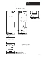
Страница 35: ...d Adapter Boards Main Logic Control Board A Quad B Board 22 TB5 MCB 11 1 TB4 F1 F2 SW1 10 A Quad B Board TB3 1 1 S1 Main Logic Control Board 1 TB2 2 1 TB1 Top View of Controller Display Board Memory Board Ground Stud 1 F3 provided on 15 22 5A units only 15A Bussmann KLM10 or equivalent 22 5A Bussmann FNQ6 1 4 or equivalent F31 ...

Страница 36: ...ore the average power level at which the drive will fault Refer to Chapter 10 for detailed switch setting information A Quad B Encoder Output Switch S1 S1 selects the line count that will be output from the A Quad B Board ATTENTION Incorrect setting of S1 can cause erratic and or improper machine motion which may result in personal injury or equipment damage Assure that switch S1 has been properly...

Страница 37: ...device Important For all IMC classic products IMC 110 12x the normal line counts per cycle of the encoder must be divided by two since the drive will see two markers per cycle Example using an IMC 12x Controller With switch S1 set to 1024 lines per revolution S1 2 OFF S1 1 ON the lines per cycle of the position feedback device located in the Feedback Parameters File must be 2048 1024 x 4 4096 2 20...

Страница 38: ...Chapter 5 Inputs Outputs and Switch Settings 5 8 End of Chapter ...

Страница 39: ...d into several different sections as shown in Figure 6 1 Figure 6 1 LCD Display Level Indicator Parameter Name Parameter Number Parameter Value When power is applied to the 1391 DES the Basic Display see Figure 6 4 will be shown The Basic Display alternates every 2 seconds between the two displays shown The alternating display indicates that the drive is functioning normally Keypad Description The...

Страница 40: ...es will be described as required Left Arrow Key This key is used to scroll through parameters or move the cursor when modifying parameters Other key functions will be described as needed Right Arrow Key The Right Arrow key can be used to scroll through parameters or move the cursor when modifying Other key functions will be described when required Enter Key The Enter key is used to make a selectio...

Страница 41: ... configuration parameters listed below This level of programming allows parameter modification to some of the View level parameters and the other parameters listed The Modify level is denoted by two dots in the upper left corner of the display see Figure 6 1 68 Bandwidth Maximum 69 Auto Tune Friction Compensation 128 EEprom Functions 130 Drive OK Mode 131 Language Select 132 Velocity Mode Select 1...

Страница 42: ...ror 44 External Torque Reference 46 Id Flux Current Reference 47 IT Protection Limit 48 Bridge Current Limit 49 Current Feedback Scale 58 D A 1 Command Value 59 D A 2 Command Value 129 Units Select 135 Up to Speed Tolerance 136 Drive Address 155 Rated Motor Current 158 Current Rate Limit 172 Velocity Loop Integrator Preset Value 181 Motor Inertia 199 Friction Compensation 200 Friction Hysteresis 2...

Страница 43: ... Keys to Modify Enter to Select and Right Arrow Enter to Cancel View modify parameters Use Up Down Arrow Keys to View Faults View current drive status View current fault status Save retrieve drive parameters Auto tune the servo drive Setup drive with motor data Maintenance Lev el Parameters Status Messages Fault Messages EEprom func parameter 128 Auto tune the servo drive Motor type parameter 154 ...

Страница 44: ...1391 DES Basic Display The three parameter levels can be accessed by using the key combinations described below The parameter level can be confirmed by observing the number of dots in the upper left corner of the display To Access the View Level Press the Down Arrow key once the View Level will be active Enter To Access the Modify Level Press the up down and left arrow keys simultaneously and rele...

Страница 45: ...A Numeric parameter contains a numeric value When this type of parameter is displayed in the Modify or Maintenance levels pressing the Down Arrow key will cause the cursor to flash Pressing the right or left arrow keys will then move the cursor one digit to the right or left The Up and Down Arrow keys can then be used to scroll to the desired value When the parameter is set to the desired value pr...

Страница 46: ...t personnel injury and or machine damage caused by improper programming parameter names followed by an asterisk should only be modified by qualified personnel Parameter 00 Reset Display Faults Rst Disp Flts This parameter clears display faults Parameter Type View Modify in Maintenance level only Parameter 03 Drive Size The current drive size in amperes as read from the drive on power up is contain...

Страница 47: ... Not Used bit 10 External A D Conversion Fault bit 11 Internal A D Conversion Fault bit 12 Not Used bit 13 Not Used bit 14 EEprom Fault bit 15 Auto Tune Fault Parameter 07 Drive Status Drv Status A 16 bit binary word represents the drive status A 1 indicates that a particular state exists If a 0 is displayed that state does not exist Refer to the list below for an explanation of the individual bit...

Страница 48: ...internal digital velocity control has been selected in parameter 132 The data contained in this parameter represents the whole number of the velocity reference Parameter Type View modify in Maintenance level Minimum Value 8000 rpm Maximum Value 8000 rpm Parameter 18 Velocity Reference Fraction Vel Ref Fract The fractional part of an external velocity reference when internal digital velocity contro...

Страница 49: ...nce level Minimum Value 8000 rpm Maximum Value 8000 rpm Parameter 23 Resolver Turns The number of resolver electrical turns is supplied by this parameter When these values reach maximum the value drops to zero and begins to again count up and down Parameter Type View only in Maintenance level Minimum Value 32768 Maximum Value 32767 Parameter 24 Resolver Position Feedback Resolver Posn This paramet...

Страница 50: ...orque Current Reference Iq Current Ref This parameter displays the torque producing current reference Parameter Type View only in all levels Minimum Value 300 rated motor current or 2 times drive rating whichever is less Maximum Value 300 rated motor current Parameter 46 Id Flux Current Reference Id Current Ref The flux producing current reference is displayed by this parameter Parameter Type View...

Страница 51: ... 14 1 11 3 8 4 5 6 2 8 Parameter 49 Value 15 14 13 12 11 10 9 8 7 6 5 4 3 2 1 0 Parameter 50 Current Feedback Rated Cur Fdbk Rated This parameter displays the actual motor current scaling based on current feedback scale and drive size parameters 49 3 Parameter Type View only in all levels Minimum Value Drive size 16 Maximum Value Drive size Parameter 51 Current Limit The real time current limit is...

Страница 52: ...by the auto tune cycle is represented through this parameter Parameter Type View only in Modify level and Maintenance level Minimum Value 0 Maximum Value 100 rated motor current Parameter 128 EEprom Functions EEprom Func This parameter allows the user to initialize recall or save the parameters stored in the EEprom Entering the number listed will cause the drive to perform the designated action Pa...

Страница 53: ...e typically 0 to 10V DC 1 Digital Inp internal digital reference parameters 17 18 2 A D Digt1 analog and digital reference parameters 57 17 18 3 Zero Input zero velocity reference Parameter 133 Torque Select This parameter selects the torque command source within the drive When operating the drive in velocity mode set to Velocity Mode 1 When operating in torque mode using S Class MAX IMC 121 123 s...

Страница 54: ...p This parameter specifies the largest change in the velocity command per velocity loop sample that will be allowed except when an immediate stop causes the velocity limit block to be bypassed Parameter Type View modify in Modify level and Maintenance level Minimum Value 5 revs per sec sec Maximum Value 22216 revs per sec sec Default Value 22216 revs per sec sec Parameter 154 Motor Type The catalo...

Страница 55: ...urrent Rate Limit Cur Rate Limit The largest change in the current reference per velocity loop sample that will be allowed is specified through this parameter Value shown on the display is in amperes second Description is based on percentage of motor rating to allow interpretation of value Parameter Type View modify in Maintenance level Minimum Value 130 rated motor current per second Maximum Valu...

Страница 56: ...15 6 rpm Default Value 1 rpm Parameter 172 Velocity Loop Integrator Preset Intg Prest Val The velocity loop integrator will be set to the value in this parameter when the drive transitions into the run state Parameter Type View modify in Maintenance level Minimum Value 200 rated motor current Maximum Value 200 rated motor current Default Value 0 Parameter 181 Motor Inertia Displays the time it wil...

Страница 57: ...eter Type View modify in Modify level and Maintenance level Minimum Value 0 rads second Maximum Value 30000 rads second Default Value 30000 rads second Parameter 185 Lead Lag Velocity Fdbk Filter Gain Lead Lag Gain Specifies the gain of the velocity feedback filter A value of 1 00 disables the filter Parameter Type View modify in Modify level and Maintenance level Minimum Value 10 00 lag Maximum V...

Страница 58: ...eter 190 Auto Tune Select Auto Tune Sel This parameter initiates an auto tune cycle which measures the Auto Tune Inertia parameter 189 and Auto Tune Friction parameter 69 by accelerating the motor up to the Auto Tune Velocity parameter 187 at the Auto Tune Current Limit parameter 188 The parameter also calculates the gains based on auto tune information Parameter Type View modify in Modify level a...

Страница 59: ... input command The desired input velocity command voltage to motor rpm scaling is accomplished with the Analog Velocity Gain parameter 211 The default setting is 500 rpm volt Use the following formula if the maximum motor speed rpm and maximum velocity command volts are known Maximum Desired Motor RPM Maximum Velocity Command RPM Volts for example 3000 RPM Maximum 8V DC Maximum Command 375 RPM Vol...

Страница 60: ...nce level Minimum Value 0 rpm Maximum Value 8000 rpm Default Value Set by Setup drive with motor data routine Parameter 224 Id Percent Limit Id Percnt Lim This parameter is associated with the field weakening function Parameter Type View modify in Maintenance level Minimum Value 0 rpm Maximum Value 100 Default Value 70 Parameter 233 Cable Compensation Cable Comp This parameter is set based on the ...

Страница 61: ...direct Sink2 This parameter specifies the sink parameter for Indirect 2 Parameters 245 and 246 define a link between two other parameters The value of the parameter specified by parameter 246 is written to the parameter specified by parameter 245 once every velocity loop update Parameter Type View modify in Maintenance level Minimum Value 0 Maximum Value 254 Default Value 59 Parameter 246 Indirect...

Страница 62: ... View modify in Maintenance level Default Value 1 No 1 No has not been setup 0 Yes has been setup Parameter 253 Display Software Version Display SW Ver This parameter displays the current display software version number Parameter Type View only in all levels Parameter 254 Drive Software Version Drive SW Ver This parameter displays the current drive software version number Parameter Type View only ...

Страница 63: ...ing Mounting dimensions for the 1391 DES Servo Drive can be found in Appendix A Chapter 2 provides information on power dissipation and environmental specifications The drive must be located on a flat rigid vertical surface and must not be subjected to shock vibration moisture oil mist dust corrosive vapors etc or temperatures that exceed 60 C 140 F ambient Drives can be mounted adjacent to each o...

Страница 64: ...cutting drilling tapping and welding can be accomplished with the drive removed from the enclosure The drive is of the open type construction and any metal debris must be kept from falling into it Metal debris or other foreign matter may become lodged in the circuitry resulting in component damage ...

Страница 65: ... excessive voltage drops Consult the National Electrical or local Code for factors on ambient conditions length etc or the Allen Bradley Sales Representative in your area for further information Shielding Reasonable care must be taken when connecting and routing power and signal wiring on a machine or system Radiated noise from nearby relays relay coils should have surge suppressors transformers o...

Страница 66: ...wer and can pickup PWM radiation Isolation from control devices may be required Grounding All equipment and components of a machine or process system shall have their chassis connected to a common earth ground point This ground system provides a low impedance path that helps minimize shock hazards to personnel and damage to equipment caused by short circuits transient overvoltages and accidental c...

Страница 67: ...iring The motor wiring size is determined by the continuous and overload current requirements RMS Duty Cycle NEC and local codes In general motors operated from the following drives would not require wire sizes larger than those accepted by TB5 but codes must be followed In addition the motor leads must be twisted throughout their entire length to minimize radiated electrical noise Allen Bradley 1...

Страница 68: ...hutdown Without this power supply relay erroneous counts could be received by the IMC Classic Controller when AC power is cycled to the drive but not the controller When power is removed to the drive the AQB Board will not have control voltage However the board will still receive the encoder voltage 5V DC or 8 15V DC from the IMC Classic Controller As the drive power is cycled it will briefly outp...

Страница 69: ...use ratings shown in Table 7 C are the highest ratings allowed in a 25 C 77 F ambient temperature Higher electrical enclosure ambient temperatures will require fuses with higher current ratings Consult fuse manufacturer s derating data Fuses larger than those listed below may result in transformer damage Table 7 C Fuse Current Rating Amperes Primary Voltage 208V AC 240V AC 380V AC 415V AC 480V AC ...

Страница 70: ...read and understand the following procedure before beginning the Start Up Procedure If an event does not occur while performing this start up Do Not Proceed Remove Power by opening the branch circuit disconnect device and correct the malfunction before continuing ATTENTION This product contains stored energy devices To avoid hazard of electrical shock verify that all voltage on the capacitors has ...

Страница 71: ...230V AC TB4 21 to TB4 19 36V AC TP13 to TP12 12V DC TP14 to TP12 12V DC 7 Remove all power to the transformer 8 The wires connected to terminals 9 and 10 of TB2 must be marked and removed to allow for local operation of the enable circuit Connect a suitable temporary switch between these terminals and insulate the switch connections 9 Once control connections are made a Open the enable switch the ...

Страница 72: ...sly then within 4 seconds press the Up Left and Enter keys Access parameter 252 and enter a value of 1 press Enter Then press the Left or Right Arrow keys to access parameter 128 Select Save to save the parameters to EEprom press Enter Cycle all power and proceed 11 The display will now read START UP PROCEDURE press the Enter key to continue Display setup drive with motor data Press Enter to conti...

Страница 73: ... resolver wiring 15 The display will now read disable drive to continue Disable the drive by opening the Enable input leaving the contactor energized Display press enter to exit motor test press Enter 16 The display will now read zero analog velocity offset press Enter In this mode the drive will automatically adjust out any offset while the motor remains at zero speed When the display reads enabl...

Страница 74: ...imum velocity command If the maximum command voltage exceeds the normal maximum level these values will limit the speed of the motor If unknown leave setting at the default value Important Factory default values are set 10 over the maximum rated speed of the motor as shown in Table 9 A Press the Enter key to continue 19 The drive will prompt for the resolver cable length being used parameter 233 C...

Страница 75: ...ent and take precautions to guard against personnel injury or machine damage Depending on the inertia of the system several revolutions of the motor may occur Axis movement must take place for the drive to complete the auto tune cycle 24 The drive will display the message DANGER MTR REVS POSSIBLE This means that the motor may make revolutions during auto tune causing machine movement Important If ...

Страница 76: ...y disconnected apply power and check operation If motor rotation is incorrect reverse the Velocity Command Input leads at TB2 1 2 29 If the drive is to be run in torque control with S Class IMC 123 Controllers etc set parameter 133 Torque Select to A D Torque Block 30 Enter the Maintenance programming level by pressing the up down and left arrow keys simultaneously then within 4 seconds simultaneo...

Страница 77: ...ease the value until the motor shaft does not rotate e Perform step 36 f De energize the Enable input remove power and reconnect all wiring if applicable 33 Analog Velocity Gain a Apply power to the drive b Energize the contactor M but Do Not Enable the drive c Access the Analog Velocity Gain parameter 211 Modify level d The drive will allow you to enter a value for the Analog Velocity Gain The de...

Страница 78: ...d Perform step 36 e Remove power and reconnect all wiring if applicable 36 Saving Current Parameters to EEprom If this step was just performed proceed to the System Compensation Procedure or step 39 a Access parameter 128 EEprom Functions and select Save followed by the Enter key This will load the parameter values into memory If no additional changes are required press the Up Arrow key and Enter ...

Страница 79: ...y overshoot of 20 30 on accel and decel is optimal on a point to point positioning or velocity controlled system The Critically Damped curve is desirable on a contouring or metal removing system Parameter 169 Ki Velocity Loop should be adjusted so that the motor achieves the commanded speed or final position as quickly as possible with little or no overshoot In addition to the dynamic response the...

Страница 80: ... Decel pots to the maximum counterclockwise position minimum accel decel time Important All potentiometers on the module are 15 turn bi directional The Local Speed pots are setup such that counterclockwise rotation will increase output and clockwise rotation will decrease output Counterclockwise rotation of the Accel Decel pots will decrease time while clockwise rotation will increase time 5 Apply...

Страница 81: ...nt Changing direction with the speed input follows the accel decel times set on the module 8 Move the meter leads to drive terminals 1 2 of TB2 The meter should indicate a voltage of approximately 10V DC 9 Rotate the Accel and Decel pots located on the module front panel approximately 7 turns 10 De energize the SEL 1 input terminals 1 2 of J2 and note the time needed for the meter voltage to reach...

Страница 82: ...rive and module Initiate a Start command by selecting speed input SEL1 Command a speed through the speed pot SPD 1 that represents approximately 10 of maximum speed i e 1V DC The motor should rotate slowly under control following the speed pot If the motor is uncontrollable or rotates incorrectly de energize SEL 1 Remove all power and check wiring If the application requires reverse direction use ...

Страница 83: ...cel Accel SPD 1 SPD 3 SPD 4 J2 J2 J2 J1 J3 Local Speed 3 Local Speed 4 24V DC or 115V AC 24V DC or 115V AC R L 1 17 18 19 20 Bypass Bypass J1 J1 J1 J1 J2 Invert FWD REV M Enable Select 21 22 Deadman 10V DC to TB2 1 to TB2 2 115V AC Power Supply 11 10 7 8 R L 2 R L 2 11 12 R L 3 R L 3 15 16 R L 4 R L 4 1 2 SEL 1 SEL 1 5 6 SEL 2 SEL 2 9 10 SEL 3 SEL 3 13 14 SEL 4 SEL 4 1 2 CR TYPICAL CONTROL CIRCUIT...

Страница 84: ...ter 8 Start Up 8 15 Figure 8 3 Linear Accel Decel Control Module Dimensions 7 25 184 2 0 5 12 7 4 25 108 0 0 41 10 3 2 75 69 9 0 75 19 1 0 50 12 7 3 44 87 3 8 12 206 2 0 75 19 1 Dimensions are in inches mm ...

Страница 85: ...Chapter 8 Start Up 8 16 End of Chapter ...

Страница 86: ...e ÇÇÇÇÇÇ ÇÇÇÇÇÇ ÇÇÇÇÇÇ ÇÇÇÇÇÇ ÇÇÇÇÇÇ ÇÇÇÇÇÇ ÇÇÇÇÇÇ ÇÇÇÇÇÇ ÇÇÇÇÇÇ ÇÇÇÇÇÇ ÇÇÇÇÇÇ ÇÇÇÇÇÇ ÇÇÇÇÇÇ ÇÇÇÇÇÇÇÇÇÇÇ ÇÇÇÇÇÇÇÇÇÇÇ ÇÇÇÇÇÇÇÇÇÇÇ ÇÇÇÇÇÇÇÇÇÇÇ ÇÇÇÇÇÇÇÇÇÇÇ ÇÇÇÇÇÇÇÇÇÇÇ ÇÇÇÇÇÇÇÇÇÇÇ ÇÇÇÇÇÇÇÇÇÇÇ ÇÇÇÇÇÇÇÇÇÇÇ ÇÇÇÇÇÇÇÇÇÇÇ ÇÇÇÇÇÇÇÇÇÇÇ ÇÇÇÇÇÇÇÇÇÇÇ ÇÇÇÇÇÇÇÇÇÇÇ ÇÇÇÇ ÇÇÇÇ ÇÇÇÇ ÇÇÇÇ ÇÇÇÇ ÇÇÇÇ ÇÇÇÇ ÇÇÇÇ ÇÇÇÇ ÇÇÇÇ ÇÇÇÇ ÇÇÇÇ ÇÇÇÇ ÇÇÇ ÇÇÇ ÇÇÇ ÇÇÇ ÇÇÇ ÇÇÇ ÇÇÇ ÇÇÇ ÇÇÇ ÇÇÇ ÇÇÇ ÇÇÇ ÇÇÇ 0 20 40 60 80 100 120 0 40 80 120 ...

Страница 87: ...ng of either Duty Cycle Profile Decelerate Tpd Accelerate Tpa Repeat Move Cycle RPM Steady Speed Tss Rest Tr Total Cycle Time t1 t2 t3 t4 where Trms The motors RMS or average torque over the duty cycle Expressed in lb in or lb ft The same units must be used throughout the formula Tpa Motor peak torque to accelerate to maximum speed Expressed in lb in or lb ft The same units must be used throughout...

Страница 88: ...two thermal switches wired in series that will open on an overtemperature condition They are set to open at 150 C typical and close at 90 100 C typical Contacts are rated for 1A at 115V AC 1A at 24V DC 3 10 line voltage maximum 1391 DES Speed rpm 6000 4000 4000 4000 4000 4000 4000 4000 4000 3000 2000 Table 9 B Torque Plus Performance Data and Selection List 1 2 Amperes at Continuous Torque 7 1 7 0...

Страница 89: ...Chapter 9 1326 AC Servomotors 9 4 End of Chapter ...

Страница 90: ...ansformer tap to provide power to the Logic Control Board It is recommended that a 1391 Isolation Transformer be used Contact your local Allen Bradley Sales Representative if a transformer of a different type must be used Refer to Figure 10 1 and Appendix B for connection information 60 Hz Transformers Two 60 Hz transformers are available and have input ratings of 1 240 480V AC three phase 2 208 2...

Страница 91: ...sformer protection rated 115V AC 1A 24V DC 0 25A min H6 H5 H7 H9 H8 G1 G2 X1 X2 X3 Primary Voltage 240V AC 380V AC 415V AC 480V AC Connect H2 to H6 H7 to H11 H12 to H1 H3 to H6 H8 to H11 H13 to H1 H4 to H6 H9 to H11 H14 to H1 H5 to H6 H10 to H11 H15 to H1 Lines On H1 H6 H11 1391 TxxxET 50 60 Hz X1 X2 X3 Primary Voltage 208V AC 240V AC 480V AC 575V AC Connect H2 to H6 H7 to H11 H12 to H1 H3 to H6 H...

Страница 92: ...Switch settings for various drive shunt combinations are shown in Tables 10 A and B Important Accurate operation of the Duty Cycle Timer is dependent on the shunt resistor value Do Not substitute alternate values Important Setting SW1 higher than the rating of the shunt resistor may cause a blown fuse resulting in repeated overvoltage faults This will occur until the fuse is replaced and or the sw...

Страница 93: ...2 130 139 150 163 177 195 216 243 277 323 386 45A W Ext 5 Ohm Resistor 215 227 241 256 274 294 317 344 378 417 466 527 607 715 872 1115 Denotes the maximum allowable settings for factory supplied configurations ATTENTION To guard against personal injury and or equipment damage from an overheated resistor the designated duty cycle settings for factory supplied shunt resistor configurations must not...

Страница 94: ...istor ATTENTION To guard against an electrical shock hazard ensure that all power to the drive has been removed prior to performing the following procedure and the bus voltage at terminal 9 and 7 of TB5 measures 0 00 volts 1 Remove and discard the jumper present between terminals 8 and 10 of TB5 This disconnects the internal shunt resistor and fuse from the shunt regulator circuit ATTENTION When u...

Страница 95: ...tect the resistor against short circuits The shunt fuse is located on top of the drive near the circuit breaker for 15 and 22 5A drives External resistors for 22 5A and 45A drives are supplied with a fuse which must be mounted external to the drive see Appendix A for mounting dimensions Refer to Table 10 C for further shunt fuse information Table 10 C Shunt Fuse Information Drive Rating 15A 22 5A ...

Страница 96: ...al shock verify that all voltage on the capacitors has been discharged before attempting to service repair or remove this unit Voltage at terminals 9 and 7 of TB5 must be 0 00 as measured with a standard digital voltmeter or multimeter Only qualified personnel familiar with solid state control equipment and safety procedures in publication NFPA 70E should attempt this procedure ATTENTION Do not at...

Страница 97: ...acilitate this technique The procedures provided must be followed when substituting or interchanging drives or board assemblies Refer to Figure 11 1 for board and connector locations ATTENTION This drive contains ESD Electrostatic Discharge sensitive parts and assemblies Static control precautions are required when installing testing servicing or repairing this drive Component damage may result if...

Страница 98: ...2 Remove the front cover from the drive 3 Remove the Memory Board by squeezing the nylon latches 4 Install the new Memory Board 5 Apply power to the system tuning will be required Logic Control Board Substitution 1 Remove all power to the drive branch circuit 2 Remove the front cover from the drive Label and remove the ribbon cables and signal connectors TB1 and TB2 from the Logic Control Board 3 ...

Страница 99: ...nstall the Display Board and cable 8 Reconnect the signal connectors cables previously removed 9 Apply power to the system and check for proper operation tuning should not be required LED Indications The 1391 DES has two LEDs visible from the front of the drive The top LED labeled STATUS flashes green when no faults are detected by the drive and a bus undervoltage condition exists The LED will be ...

Страница 100: ...les removed The drive logic supplies are not operational 1 The logic supply fuses are blown 2 Logic supply AC voltage is missing 3 A drive malfunction has occurred but is not annunciated by the LED indicators check the status of the Drive OK contacts The application of an Enable signal by the machine position controller will cause the ENABLE LED to illuminate 1 System fault has occurred 2 Power wa...

Страница 101: ...lue Control Voltage Fault cntrl voltage Bit 4 Potential Cause All circuits are functional Fault Description None Fault Message No Active Faults Drive Overtemperature amp overtemp Bit 1 The drive contains a thermal switch on the heat sink which senses the power transistor temperature If the temperature is exceeded the LED will illuminate The logic supply 12V DC 5V DC circuits have malfunctioned fus...

Страница 102: ...ower Bus is continuously monitored If it exceeds a preset level a fault is sensed and the power supply is disabled Component on Logic Control Board has malfunctioned replace Logic Control Board Component malfunction of input A D converter External A D Conversion Fault ext A D fault Bit 10 Internal A D Conversion Fault int A D fault Bit 11 Component on Logic Control Board has malfunctioned replace ...

Страница 103: ...plying the incorrect voltage or none at all 5 The motor wiring is open 6 The motor or transformer thermal overload has tripped 7 The motor has malfunctioned 8 The coupling between motor and machine has malfunctioned 9 The feedback circuit motor to drive is open 10 Velocity Mode Select parameter 132 set incorrectly 11 Torque Select parameter 133 set incorrectly 12 Velocity limits parameters 144 145...

Страница 104: ...using excessive motor current 2 Motor voltage is exceeding the maximum value 3 The duty cycle is excessive 1 Loose parts are present in the motor 2 Through bolts are loose 3 The bearings are worn 4 Parameters 168 169 and 170 are set too high 1 Phases A B A C or B C reversed 2 Sine Cosine or Rotor leads reversed 3 Sine Cosine Rotor lead sets reversed 4 Combinations of 1 2 3 Condition No Rotation Ov...

Страница 105: ...TP20 Buffered Output Torque input TP21 Ext Current Limit Indicates the external current limit command 3V rated TP28 Signal Common TP29 30 IA IB Feedback Buffered motor current feedback signals scaled for 2 5 volts peak rated motor current TP31 Signal Common TP50 ABS Rotor Signal used to detect resolver loss Nominal value 2 596V Trip point is approximately 0 8V TP51 9V Ref Signal feeding output d a...

Страница 106: ...31 TP19 TP15 TP21 TP10 TP9 TP8 TP28 TP14 TP2 TP30 TP29 TP12 TP13 TP11 TP52 TP50 TB1 2 1 F3 Display Memory and Adapter Boards Main Logic Control Board A Quad B Board 22 TB5 MCB 11 1 TB4 F1 F2 SW1 10 1 F3 provided on 15 22 5A units only 15A Bussmann KLM10 or equivalent 22 5A Bussmann FNQ6 1 4 or equivalent Top View of Controller TP12 TP11 TP60 TP61 Display Board Memory Board Ground Stud 1 ...

Страница 107: ...Chapter 11 Troubleshooting 11 12 End of Chapter ...

Страница 108: ...1 56 293 6 9 10 228 6 6 00 152 4 5 20 132 1 3 70 93 9 0 312 7 9 Dia 0 30 7 6 0 25 6 3 0 60 15 2 Dia See Detail A Detail A Detail B 0 39 9 9 0 312 7 9 Dia Notes 1 Mounting slots and keyholes will accept 1 4 20 7 mm hardware 2 A minimum spacing of 0 312 7 9 mm is required between adjacent controllers 1 25 4 mm is recommended Ground Stud 1391 DIGITAL AC SERVO DRIVE Status Enable ALLEN BRADLEY ...

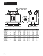
Страница 109: ...3 00 330 14 00 356 14 00 356 14 00 356 14 00 356 16 00 406 16 00 406 16 00 406 16 00 406 17 50 444 17 50 444 D 5 00 127 5 00 127 6 00 152 6 00 152 6 00 152 6 00 152 8 00 203 8 00 203 8 00 203 8 00 203 9 50 241 9 50 241 E 3 10 79 3 50 89 4 50 114 4 50 114 5 25 133 6 00 152 5 85 149 5 85 149 5 63 143 5 63 143 6 00 152 6 00 152 Weight 27 12 2 40 18 2 60 27 2 85 38 6 75 34 0 100 45 4 112 50 8 140 63 6...

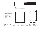
Страница 110: ...91 TA2 kVA All A 17 00 432 B 19 00 483 C 14 50 368 D 16 50 419 E 12 00 305 Weight 35 5 16 1 The following items are included with the NEMA Type 1 Enclosure Qty Description 2 Steel Mounting Channels 4 3 8 16 x 1 0 HHCS Screw 4 3 8 16 x 1 5 HHCS Screw 8 3 8 Flat Washer 8 3 8 Split Lock Washer 8 3 8 16 Hex Nuts A B D C E Front Side ...

Страница 111: ...rnal Shunt Resistor and Fuse Dimensions Dimensions are in inches and millimeters 12 75 323 8 14 00 355 6 1 87 47 5 5 38 136 6 1 13 28 7 2 25 57 1 0 281 x 0 562 7 1 x 14 2 2 81 71 4 0 91 23 1 0 16 4 1 1 34 34 0 0 203 5 2 Dia w 0 343 8 7 Dia C B ...

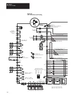
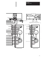
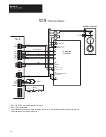
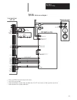
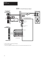
Страница 112: ...1391 DES 9 Series Interconnect Drawing 1391 DES Interconnect Drawing The 1391 DES Interconnect Drawing is presented on pages B 2 and B 3 Refer to the Notes listed below when using this drawing Notes 1 Power Wiring unless Noted 15A 12 AWG 2 5 mm2 min 75 degrees C min 22 5A 10 AWG 4 mm2 min 75 degrees C min 45A 8 AWG 6 mm2 min 75 degrees C min 2 Signal Wiring 18 AWG 0 75 mm2 min 3 Allen Bradley Supp...

Страница 113: ...UPPLY 36V AC FROM MOTOR GROUND 1326 CFUXX CABLE FROM TB1 1 DS2 GREEN ENABLE DROK CLOSED OK 120V AC 1 AMP CONNECT TO GROUND STUD PHASE SENSITIVE FROM MOTOR CABLE EMI SHIELD RUN SEE NOTE 5 REFER TO CHAPTER 5 FOR M CONTACT RATINGS SEE NOTE 5 SEE NOTE 5 ENCODER OUTPUT TO POSITION CONTROLLER NOTE 2 Phase Insensitive ROUTE SEPARATELY FROM CONTROL AND FEEDBACK WIRING PHASE INSENSITIVE GND STUD A A B B Z ...

Страница 114: ...26AB CXX AND 1326AB B4X Y SECONDARY X SECONDARY CABINET GROUND BUS WHT BLK BLK RED BLK GRN BRANCH CIRCUIT DISCONNECT NOTE 1 NOTE 6 DROK M M EMI SHIELD B G H I F 8 3 2 1 6 4 C D A E 5 9 3 2 1 8 7 6 9 5 C G H I D E F A B C B A F E D G H I J A B C D E F G H I J INDICATES COMPONENT LOCATED IN CONTROLLER RED WHT YEL WHT R2 RED WHT YEL WHT TO CUSTOMER FAULT CIRCUIT BRAKE WHEN SUPPLIED 1 C T NOT REQUIRED...

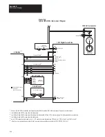
Страница 115: ...DRIVE DR RET SHLD DRIVE FAST I O CH A HI CH A LO SHLD CH B HI CH B LO SHLD CH Z HI CH Z LO ENCODER ENCODER POWER 1391 Digital Servo Drive A A B B Z Z 5V COMMON VELOCITY COM VELOCITY COM DROK 115V AC 1A CLOSED OK CONTACTOR Stop Reset P B CR2 115V AC Brake when supplied Motor Resolver K1 K2 B1 B2 CR CR2 24V RES PB RES PB RESET STRING IN STRING OUT ESTOP DRIVE ENABLE M 1326 AC Servomotor 1 3 4 5 6 7 ...

Страница 116: ...NG OUT STRING IN ESTOP FAST DRIVE DR RET SHLD DRIVE 0 ROT LO RESOLVER 0 CH A HI CH A LO SHLD CH B HI CH B LO CH Z HI CH Z LO SHLD ENCODER 0 5V 5V RET 15V 15V RET SHLD EXT PWR EXT RET ENCODER POWER 1391 Digital Servo Drive A A B B Z Z 5V COMMON VELOCITY COM VELOCITY COM DROK 115V AC 1A CLOSED OK M CONTACTOR CR2 115V AC Brake when supplied Motor Resolver Encoder Feedback K1 K2 B1 B2 CR M 1326 AC Ser...

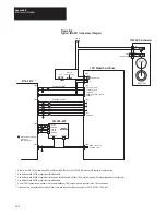
Страница 117: ... RESET STRING OUT STRING IN ESTOP FAST IN A X I S x Stop Reset P B Axis Overtravel Remote Hardwired Stop CR CR2 115V AC Brake when supplied Motor Resolver 1391 CAQB Cable 2 Male D Shell Connector to Axis Connector on IMC Module K1 K2 B1 B2 CR M 1326 AC Servomotor Termination Panel 1771 HT3 IMC Module 1 3 4 5 6 7 8 9 10 13 14 2 1 17 18 11 TB4 TB2 TB3 TB2 12 DRIVE ENABLE A X I S x CR2 CR2 1391 Digit...

Страница 118: ...Y axis connections TB3 are identical 6 If the drive is to be operated as a torque block command wires should be connected to 1391 DES TB2 15 16 17 1391 Digital Servo Drive A A B B Z Z 5V COMMON VELOCITY COM VELOCITY COM COMMON ENABLE SOURCE 23V DC ENABLE DROK 115V AC 1A CLOSED OK CONTACTOR MAX CONTROL 12V DC 12V DC COMMON 5V DC COMMON CR LPS 455 Axis Overtravel Remote Hardwired Stop 115V AC Brake ...

Страница 119: ... for Axis 3 6 If the drive is to be operated as a torque block command wires should be connected to 1391 DES TB2 15 16 17 1391 Digital Servo Drive A A B B Z Z 5V COMMON VELOCITY COM VELOCITY COM COMMON ENABLE SOURCE 23V DC ENABLE DROK 115V AC 1A CLOSED OK CONTACTOR 4100 20x 15V DC 15V DC COMMON 5V DC COMMON CR LPS 455 15 Axis Overtravel Remote Hardwired Stop 115V AC Brake when supplied Motor Resol...

Страница 120: ...to be operated as a torque block command wires should be connected to 1391 DES TB2 15 16 17 1391 Digital Servo Drive A A B B Z Z 5V COMMON VELOCITY COM VELOCITY COM ENABLE SOURCE 23V DC ENABLE DROK 115V AC 1A CLOSED OK CONTACTOR 4100 21x Axis Overtravel Remote Hardwired Stop 115V AC Brake when supplied Motor Resolver K1 K2 B1 B2 1326 AC Servomotor 1 3 4 5 6 9 10 1 2 11 TB4 TB2 TB4 TB3 12 12 11 13 ...

Страница 121: ...3 connections 6 If the drive is to be operated as a torque block command wires should be connected to 1391 DES TB2 15 16 17 5 12V DC Power Supply 4 3 24V DC COMMON 1391 Digital Servo Drive A A B B Z Z 5V COMMON VELOCITY COM VELOCITY COM COMMON ENABLE SOURCE 23V DC ENABLE DROK 115V AC 1A CLOSED OK CONTACTOR 4110 201x 12V DC 12V DC COMMON 5V DC COMMON CR LPS 455 Axis Overtravel Remote Hardwired Stop...

Страница 122: ...nterconnect Diagram For detailed 9 Series interconnect information please refer to the following publications Controller Publication 9 240 9 240 Integration Manual publication 8520 4 1 9 230 9 260 290 9 230 9 260 or 9 290 Integration Manual publication 8520 6 2 ...

Страница 123: ...Appendix B Interconnect Drawings B 12 End of Appendix ...

Страница 124: ...ck 20 H TB2 7 TB1 4 Green 20 G TB2 8 TB1 3 Shield Drain 20 N C TB2 9 TB1 2 Braided Shield 36 N C TB2 10 TB1 1 to Ground Stud 1326 CPABxx Motor Power Cable Servo Control Connection Wire Wire Gauge Connector 1389 AAxx 1391 AAxx Number Color AWG Pin Terminal Terminal 1 Black 12 F TB3 1 TB5 1 2 Black 12 I TB3 2 TB5 2 3 Black 12 B TB3 3 TB5 3 4 Black 16 D Brake Power Brake Power 5 Black 16 E Thermal Sw...

Страница 125: ...ld Mylar Shield 16 No Conn Ground Stud Ground Stud 1326 CVUxx Master Vernier Resolver Cable Master Wire Gauge Connector Vernier Pair Color AWG Pin Description Master 1 White 22 A Rotor 1 Black 22 B Rotor 2 2 Red 22 D Stator 1 Black 22 F Stator 3 3 Orange 22 E Stator 2 Black 22 G Stator 4 Vernier 4 Blue 22 J Rotor 1 Black 22 K Rotor 2 5 Green 22 N Stator 2 Black 22 R Stator 4 6 Violet 22 M Stator 1...

Страница 126: ...erminal Location 3 Black A TB3 1 AQB 12 Red A NOT TB3 2 Board 21 Shield Common No Connection 4 Black B TB3 4 AQB 13 White B NOT TB3 3 Board 22 Shield Common No Connection 5 Black Z TB3 5 AQB 14 Green Z NOT TB3 6 Board 23 Shield Common No Connection 7 Black 5V DC TB3 7 AQB 16 Blue Common TB3 8 Board 24 Shield Shield No Connection 9 Black Drive TB2 2 Logic 18 Yellow Drive Ret TB2 1 Control 26 Shield...

Страница 127: ...Appendix C Cable Information C 4 End of Appendix ...

Страница 128: ...D 1 Block Diagrams Objectives Appendix D provides detailed software and hardware block diagrams for the 1391 Digital AC Servo Drive You may use these to gain a better understanding of the 1391 DES software system ...

Страница 129: ...CURRENT 4096 100 RESOLVER POSITION RESOLVER TURNS 23 24 PRELOAD 159 0 5 1 SELECT TORQUE 155 SLOW VOLATILE SLOW PARAMETER PARAMETER TEST POINT FAST SOURCE FAST SINK CURRENT LIMITER RATE LIM CURRENT CUR LIM 4 0 3 2 0 bit HOLD NEGATIVE 48 POSITIVE 157 CUR LIM 156 CUR LIM VELOCITY COMMAND STOP 19 IT PROTECT LIM BRIDGE 47 GAIN A D MOTOR CURRENT 4096 RATED Iq CURRENT REF 45 158 10 BIT MOTOR TYPE 154 51 ...

Страница 130: ...58 168 Kp 130 EEPROM FUNC DRIVE SW VERSION 3 2 1 128 254 1 0 DROK bit 6 bit 6 drive state bit DRIVE FAULTS 6 bit 10 bit 11 bit 12 bit 13 bit 14 bit 15 bit 9 bit 7 bit 8 int A D conv eeprom autotune power fault overvoltage ext A D conv bit DRIVE STATUS 7 UP TO 135 bit 15 bit 12 bit 13 bit 14 bit 9 bit 10 bit 11 bit 7 bit 8 drive state at current limit FAULT LIST bit 0 v bit 3 bit 4 bit 5 bit 1 bit ...

Страница 131: ... TP9 CURRENT FEEDBACK COMMAND VELOCITY COMMAND TORQUE ANALOG OUT 1 ANALOG OUT 2 R1 R2 ROTOR SHIELD S1 S3 S2 S4 S1 S3 SHIELD S2 S4 SHIELD OVERALL SHIELD RESET COMMON ENABLE SOURCE ENABLE INPUT VELOCITY MODE SELECT TORQUE MODE SELECT 5 V DRIVE STATUS DROK TB4 17 18 TB4 DROK CONTACT 5 V FULL SCALE BUFFERED VELOCITY COMMAND BUFFERED TORQUE COMMAND 5 V FULL SCALE 5 V FULL SCALE COMMAND TP21 EXTERNAL CU...

Страница 132: ...s to the defaults listed and delete any previous values Parameters with a in the Actual column should not be changed unless you have consulted Allen Bradley Machine Designation Axis Designation Date Name General Information View Level Parameter Description Default Actual 03 Drive Size 19 Final Velocity Command 20 Velocity Feedback 45 Iq Torque Current Reference 50 Current Feedback Rated 51 Current...

Страница 133: ...mit 157 Negative Current Limit 159 Current Preload 0 168 Kp Velocity Loop 100 169 Ki Velocity Loop 6667 170 Feed Forward Gain 0 171 Static Gain 1 rpm 182 Desired Velocity Bandwidth 200 rads sec 183 Velocity Damping Selection 0 zeta 0 87 184 Velocity Low Pass Filter Bandwidth 30000 rads sec 185 Lead Lag Vel Fdbk Filter Gain 1 00 186 Lead Lag Vel Fdbk Filter Bandwidth 250 rads sec 187 Auto Tune Velo...

Страница 134: ...ference 47 IT Protection Limit 48 Bridge Current Limit 49 Current Feedback Scale 58 D A 1 Command Value 59 D A 2 Command Value 129 Units Select 0 User Units 135 Up to Speed Tolerance 19 5 rpm 136 Drive Address 1 155 Rated Motor Current 158 Current Rate Limit 172 Velocity Loop Integrator Preset Value 0 181 Motor Inertia 199 Friction Compensation 50 200 Friction Hysteresis 0 5 rpm 201 Friction Bit 1...

Страница 135: ...Appendix E Parameter Record E 8 End of Appendix ...

Страница 136: ...Notes ...

Страница 137: ...Notes ...

Страница 138: ...Notes ...

Страница 139: ...Notes ...

Страница 140: ...Notes ...

Страница 141: ...Notes ...

Страница 142: ...Notes ...

Страница 143: ...Notes ...

Страница 144: ...Notes ...

Страница 145: ...Notes ...

Страница 146: ...Y DESIGN IMPLEMENT ELECTRICAL SYSTEMS TRAIN EDUCATE MACHINE USERS SUPERVISE FLOOR OPERATIONS WHAT LEVEL OF EXPERIENCE DO YOU HAVE WITH EACH OF THE FOLLOWING PRODUCTS NONE LITTLE MODERATE EXTENSIVE PROGRAMMABLE CONTROL AC DC DRIVES PERSONAL COMPUTERS NC CNC CONTROLS DATA COMMUNICATIONS LAN RATE THE OVERALL QUALITY OF THIS MANUAL BY CIRCLING YOUR RESPONSE BELOW 1 POOR 5 EXCELLENT HELPFULNESS OF INDE...

Страница 147: ...E NO POSTAGE NECESSARY IF MAILED IN THE UNITED STATES BUSINESS REPLY MAIL PERMIT NO 413 MEQUON WI POSTAGE WILL BE PAID BY ADDRESSEE ALLEN BRADLEY Attn Marketing Communications P O Box 760 Mequon WI 53092 9907 FIRST CLASS ...

Страница 148: ...IMC is a trademark of Allen Bradley Company Inc ...

Страница 149: ...1391 DES Digital AC Servo Drive 1391 DES Digital AC Servo Drive User Manual Publication 1391 5 3 June 1994 Publication 1391 5 3 June 1994 User Manual ...

Страница 150: ... 2975 60222 LATIN AMERICA HEADQUARTERS 1201 South Second Street Milwaukee WI 53204 USA Tel 414 382 2000 Telex 43 11 016 FAX 414 382 2400 ASIA PACIFIC HEADQUARTERS Allen Bradley Hong Kong Ltd Room 1006 Block B Sea View Estate 2 8 Watson Road Hong Kong Tel 852 887 4788 Telex 64347 ABHKG HX FAX 852 510 9436 852 510 9420 CANADA HEADQUARTERS Allen Bradley Canada Limited 135 Dundas Street Cambridge Onta...

Отзывы: