Chapter 4
Description of Operation
4-6
ATTENTION: The user has the ultimate responsibility to
determine which stopping method is best suited to the applica-
tion and will meet applicable standards for operator safety.
!
Starting and Stopping must be accomplished by hardwired user supplied
elements as shown in Appendix B. Stopping modes for the 1391-DES are
outlined below. Refer to the paragraphs that follow for detailed
information. The effects described below assume that the 36V AC control
voltage has not been de-energized.
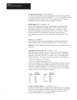
Cause
Effect on Motor
De-energize Line/DB Contactor (M) Coil
Dynamic Brake
Speed Command brought to Zero
Regenerative Brake
Open Enable Input
Regenerative Brake
DROK Opens (Fault)
Coast to Stop
Dynamic Braking
When the line/DB contactor (M) is de-energized by the control circuitry, an
inherent dynamic braking effect will occur during the DC bus decay,
provided the 36V AC logic voltage is not de-energized. The dynamic
braking effect depends on the value of the shunt regulator resistor and total
load inertia.
Important: Frequent cycling of the line/DB contactor to start/stop the
motor will reduce the life of the contactor.
Regenerative Braking
Normal run commands to the drive are performed through the Enable input
and any additional customer supplied control circuitry. Refer to Appendix
B. With input power applied, a mechanical contact closure (or solid-state
contact closure rated +15 to +30V DC, 30 mA) between TB2-9 & 10 will
cause the drive to run, provided the line/DB contactor (M) has been
energized by the control circuitry. When the Enable input is de-energized,
the maximum available reverse torque is applied to the motor in a
regenerative stopping mode, which will occur for approximately 450ms.
Coast
An internal drive fault opens the DROK contact. Coasting will only occur
if the DROK contact is not wired to the line/DB contactor coil (M) or the
Enable input circuits.
Содержание ALLEN-BRADLEY 1391-DES
Страница 1: ...User Manual 1391 DES Digital AC Servo Drive...
Страница 9: ...Chapter 1 Introduction 1 10 End of Chapter...
Страница 37: ...Chapter 5 Inputs Outputs and Switch Settings 5 8 End of Chapter...
Страница 84: ...Chapter 8 Start Up 8 16 End of Chapter...
Страница 88: ...Chapter 9 1326 AC Servomotors 9 4 End of Chapter...
Страница 106: ...Chapter 11 Troubleshooting 11 12 End of Chapter...
Страница 122: ...Appendix B Interconnect Drawings B 12 End of Appendix...
Страница 126: ...Appendix C Cable Information C 4 End of Appendix...
Страница 134: ...Appendix E Parameter Record E 8 End of Appendix...
Страница 135: ...Notes...
Страница 136: ...Notes...
Страница 137: ...Notes...
Страница 138: ...Notes...
Страница 139: ...Notes...
Страница 140: ...Notes...
Страница 141: ...Notes...
Страница 142: ...Notes...
Страница 143: ...Notes...
Страница 144: ...Notes...
Страница 147: ...IMC is a trademark of Allen Bradley Company Inc...


