Chapter 11
Troubleshooting
11-8
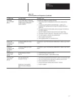
Table 11.C
General System Troubleshooting
Possible Cause
1. The velocity feedback, position feedback device or velocity command signal wiring is incorrect or
open.
2. An internal drive malfunction exists.
3. Set in torque mode incorrectly.
1. Parameters 168, 169 and 170 are set too high.
2. Position Loop Gain or Position Controller accel/decel rate is improperly set.
3. Improper grounding or shielding techniques are causing noise to be transmitted into the position
feedback or velocity command lines, causing erratic axis movement.
4. Parameter 154 is incorrectly set (servomotor is not matched to drive).
1. Parameters 156/157 are set too low.
2. Parameter 154 is incorrectly set (servomotor is not matched to drive).
3. The system inertia is excessive.
4. The system friction torque is excessive.
5. Available drive current is insufficient to supply the correct accel/decel rate.
6. Accel/Decel Ramp (parameter 146) incorrect.
7. Velocity limit (parameters 144, 145) incorrect.
8. Analog Velocity Gain (parameter 211) incorrect.
1. The drive has a malfunction
2. The drive is not enabled.
3. The contactor (M) is not energized.
4. Power transformer is supplying the incorrect voltage or none at all.
5. The motor wiring is open.
6. The motor or transformer thermal overload has tripped.
7. The motor has malfunctioned.
8. The coupling between motor and machine has malfunctioned.
9. The feedback circuit (motor to drive) is open.
10. Velocity Mode Select (parameter 132) set incorrectly.
11. Torque Select (parameter 133) set incorrectly.
12. Velocity limits (parameters 144, 145) set incorrectly.
1. 50/60 Hz line frequency may be present.
2. 100/120 Hz from a single phase logic supply may be present.
3. 180 or 360 Hz from other adjustable speed drives may be present.
4. Variable frequency (varies with motor speed) may be velocity feedback ripple or a disturbance
caused by gear teeth or ballscrew balls etc. The frequency may be a multiple of the motor power
transmission components or ballscrew speeds.
5. Recommended grounding per Appendix B has not been followed.
1. AQB Board outputs a series of encoder pulses during power-up. An intermittent connection or
removal of TB3 while powered up will cause this series of pulses to repeat.
Condition
Axis or System runs uncontrollably
Axis or System is unstable
Desired motor acceleration /
deceleration cannot be obtained
Motor does not respond to a Velocity
Command
Presence of noise on Command or
resolver signal wires
Position controller faults on excess
encoder counts during power-up.
Содержание ALLEN-BRADLEY 1391-DES
Страница 1: ...User Manual 1391 DES Digital AC Servo Drive...
Страница 9: ...Chapter 1 Introduction 1 10 End of Chapter...
Страница 37: ...Chapter 5 Inputs Outputs and Switch Settings 5 8 End of Chapter...
Страница 84: ...Chapter 8 Start Up 8 16 End of Chapter...
Страница 88: ...Chapter 9 1326 AC Servomotors 9 4 End of Chapter...
Страница 106: ...Chapter 11 Troubleshooting 11 12 End of Chapter...
Страница 122: ...Appendix B Interconnect Drawings B 12 End of Appendix...
Страница 126: ...Appendix C Cable Information C 4 End of Appendix...
Страница 134: ...Appendix E Parameter Record E 8 End of Appendix...
Страница 135: ...Notes...
Страница 136: ...Notes...
Страница 137: ...Notes...
Страница 138: ...Notes...
Страница 139: ...Notes...
Страница 140: ...Notes...
Страница 141: ...Notes...
Страница 142: ...Notes...
Страница 143: ...Notes...
Страница 144: ...Notes...
Страница 147: ...IMC is a trademark of Allen Bradley Company Inc...


