Front panel functions
SOURCE INDICATOR
During normal operation the left side display shows the selected source. The line
inputs are shown as L-1, L-2 and L-3. The phono input (if the phono module is
fitted), is shown as P-1. The digital inputs (if the DAC module is fitted), are shown
as D-1 to D-5.
It is possible to change the source with the rotating knob (17), when navigation
mode is activated. When changing settings (see “MUTE, GAIN, CARTRIDGE
LOADING AND BALANCE SETTINGS” and “MENU FUNCTIONS”), the source
indicator display will show the current item being changed.
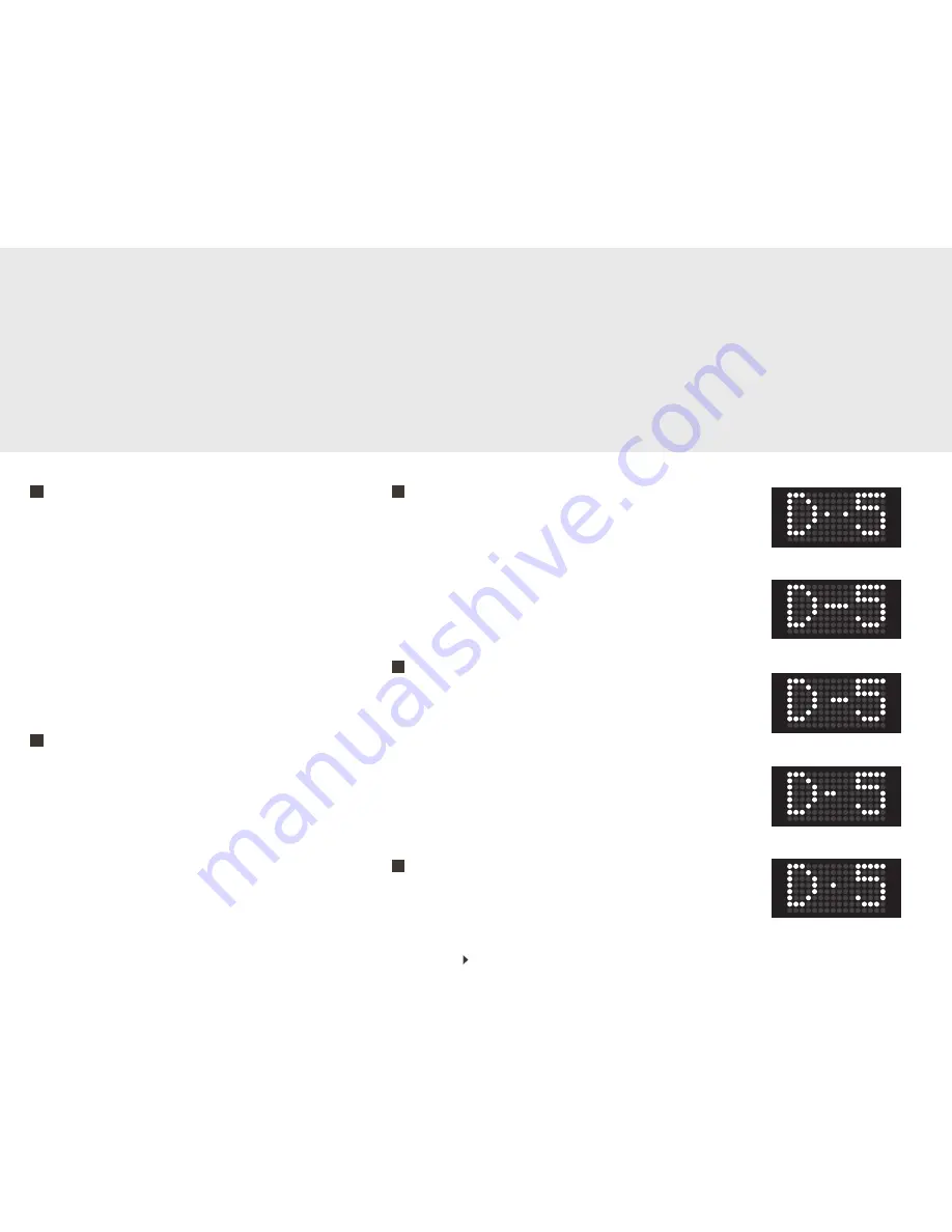
When playing digital sources, the line separating D and the number, will change to
a number of dots depending on the format being played. Two dots with a space in
between (
Fig. a
) means DSD (available on the USB input only). 1-4 dots without
spaces indicate different PCM formats (
Fig. b, c, d, e
).
MUTE, GAIN, CARTRIDGE LOADING AND BALANCE SETTINGS
The mute button has multiple functions. When you press this button briefly, it will
mute the speaker outputs of the amplifier, and also the pre outs with the standard
configuration (see “MENU FUNCTIONS” page 7). A minus and a speaker symbol
will be shown on the right side display, indicating that the outputs of the amplifier
are muted.
The other functions of the mute button, allows you to set the gain of the input, to
set the cartridge loading for the phono stage, and to adjust the left/right balance.
These settings can also be changed using the remote control.
See “MENU FUNCTIONS”.
INDIVIDUAL GAIN SETTINGS
Press and hold the mute button (13) one second to activate the individual gain set-
ting mode. When activated, the left side display will show “Gain”, and the current
gain setting will be shown on the right side display (
Fig. c
). This mode will let you
choose between 6 gain setting for the analogue inputs and 4 settings for the digital
inputs. Turning the volume control knob (17) counter-clockwise will decrease the
gain setting, whilst turning the knob clockwise increases the gain setting. Pressing
the mute button (13) briefly will deactivate the gain setting mode, and the usual
display will return.
CARTRIDGE LOADING ADJUSTMENT
With the RIAA/phono input selected, press and hold the mute button (13) for
more than three seconds to enter cartridge loading adjustment mode. The left side
display will show “Rin” and the right side display will show the current setting.
Use the volume control knob (17) to set the cartridge loading. Deactivate the
cartridge loading adjustment by pressing the mute button briefly.
NOTE!
Pressing and holding the mute button (13) for less than three seconds, with the
RIAA selected, will activate the gain setting mode. The button needs to be held for
more than three seconds to activate the cartridge loading adjustment mode.
BALANCE SETTING ADJUSTMENT
The balance between the left and right channel, can be adjusted in 1dB steps. The
balance setting is common for all inputs. To enter the balance setting mode, press
and hold the mute button (13) for more than five seconds. The left side display will
12
13
13
13
13
Page 9
Fig. a
Fig. b
Fig. c
Fig. d
Fig. e
Содержание U-150
Страница 1: ...U 150 Integrated Amplifier User s guide...


