Procedures
ATP-CNX-020 Rel. 1.2, Doc. Rev. 01.06
7
Aastra CNX Installation and Setup Procedures
Starting up and checking the Aastra CNX
Apply power to the Aastra CNX
To start up the Aastra CNX, insert the CompactFlash card into slot 1 of the unit and apply power
from the power source.
Starts diagnostic test routines on the Aastra CNX.
Checks for a flash memory card in CompactFlash slot 1 of the Aastra CNX chassis.
Initializes the Aastra CNX and, if successful, resets all LEDs to their normal state.
Starts a one-time software script that allows you to setup your network settings (See Step 7).
Powering up a new Aastra CNX:
Alarm Indicators
a. Check that the Status LED is not ON Red. If the Status LED is
ON Red, an alarm condition exists in the unit. Contact your System Administrator.
NOTE: During bootup of the Aastra CNX, the Status LED is ON Red
for 1 second. This is a normal condition at bootup.
b. When the T1/E1 port(s) are enabled, check that the T1/E1 LEDs
on the bottom row are OFF. If the T1/E1 LED(s) on the bottom row are ON Amber,
a yellow alarm is present on the T1/E1 link. If the T1/E1 LEDs are ON Red, a
Red alarm is present on the T1/E1 link. Contact your System Administrator.
Check the LEDs
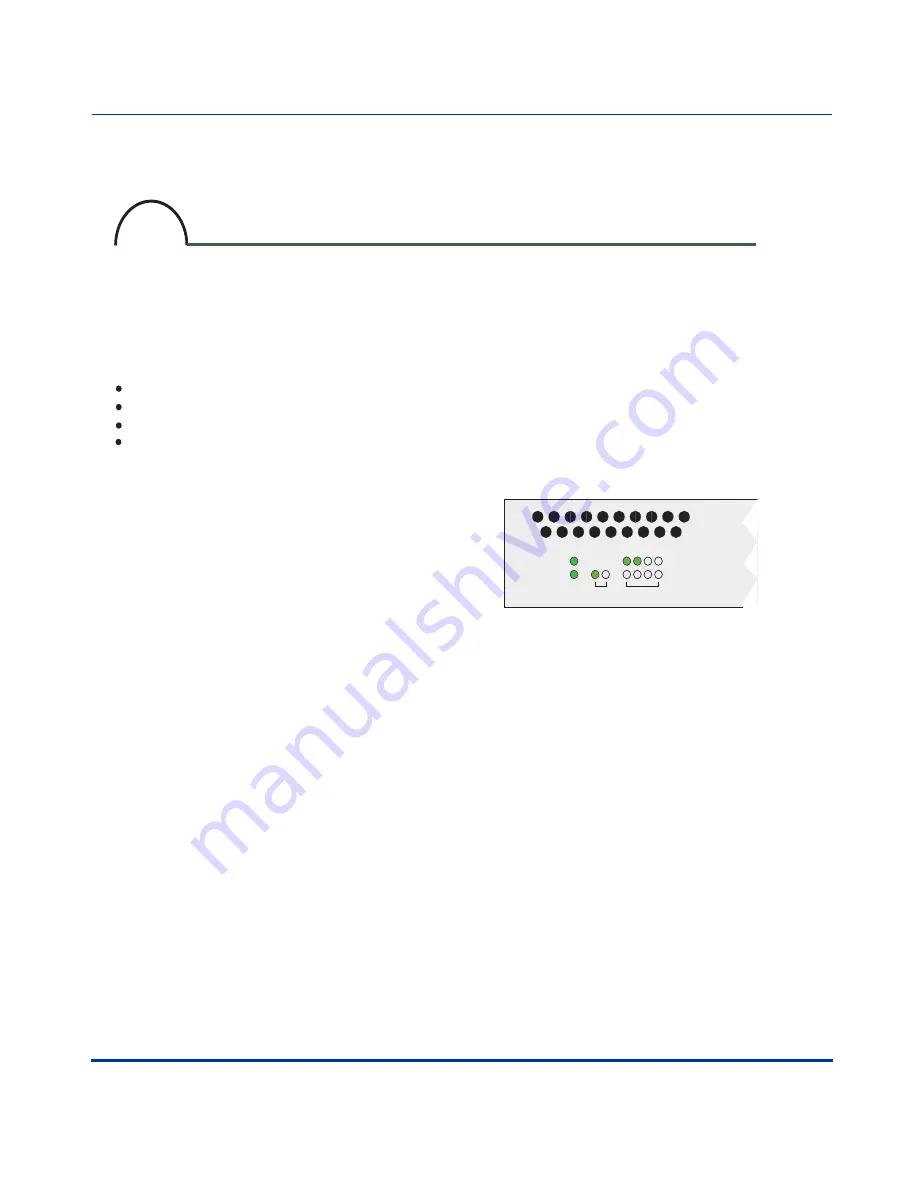
a. Check the common LEDs on the front panel.
The Power and Status LEDs should be ON (green)
indicating the Aastra CNX is ready to take calls.
b. Check the ENET LEDs on the front panel.
If your Aastra CNX has a physical Ethernet link to your
network from the 10/100 ENET ports 1 or 2 on the back
panel, and no alarms are present, the ENET LEDs
1 and/or 2 should be ON (green).
NOTE: The ENET LEDs FLASH (green) when
there is Rx/Tx activity.
c. The T1/E1 ports are disabled by default in the
Aastra CNX software configuration. The top row of T1/E1
LEDs should be OFF. To enable these ports and check the
LEDs, the System Administrator must enable the
T1/E1 ports using the Aastra CNX GUI.
Startup and check the Aastra CNX
6
POWER
STATUS
ALARM
ACTIVE
1
10/100 ENET T1 / E1
2
1 2 3 4


