background image

9


/


13


you will have to replace the holding device. 
To do this, follow the next steps:   

a. Lift up the far end of the wheel fork, then take it out from the groove on

the carriage.

b. Insert the frame adaptor into the groove (Fig. 9).

Fig. 9

Fig. 10 

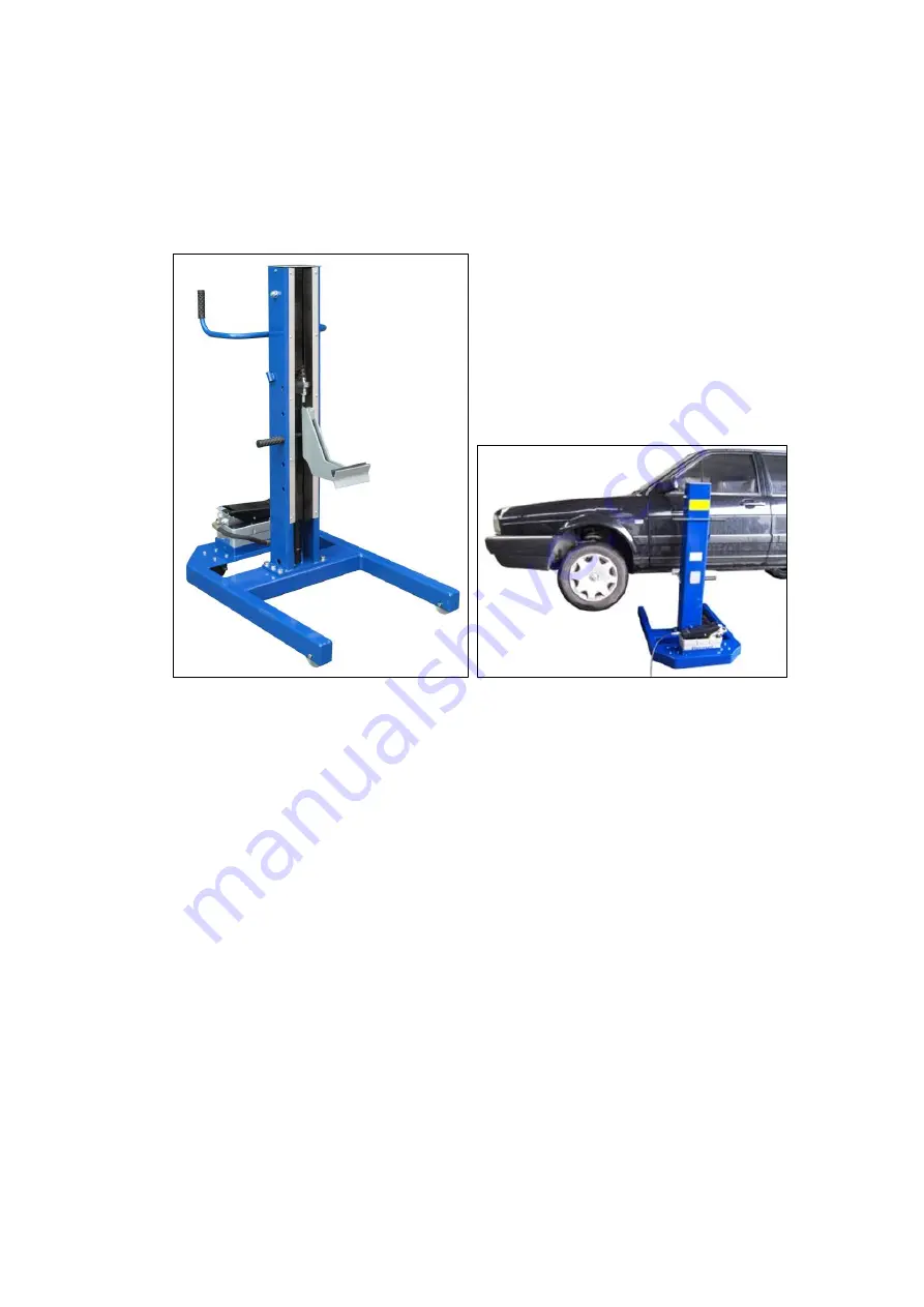
10. While using the frame adapter to lift up the vehicle, remember to position

the adapter on the gravity center line of the vehicle. That is to lift up the
whole side of the vehicle.(Fig.10)

Suggestion:
a. The position on the frame near under the vehicle’s side-view mirror is a

good place for the adapter..

b. Remember that the holding place has to be a strongest area of the

frame with stability. Never to be in the center of the vehicle or at the
back.

Содержание AutoLift AL-182093

Страница 1: ...AUSE INJURY OR DEATH Specifications subject to change without notice Note While all due care and attention has been taken in the preparation of this document Advance AutoQuip shall not be liable for any inaccuracies or omissions which may occur therein INSTALLATION MANUAL OPERATION INSTRUCTIONS READ FIRST DO NOT use the machine until you read and understand all the dangers warnings and cautions in...

Страница 2: ...ks to wheels an easy displacement is its main feature 3 It has been projected for a sure use thanks to an easy and efficient manual block The safety pin 4 The manual safety pin permits the column carriage to be blocked during the working operation 5 Air hydraulic pump output pressure 350bar Max Basic Specification Description Capacity Lifting Height Overall Height Overall Width Overall Length AIR ...

Страница 3: ...carry the weight to hoist a cover with a hole for the spindle and a vertical hook at the front for holding the different attachments 3 Air hydraulic foot pump Behind the column there is the air hydraulic foot pump It supply the power to the cylinder for lifting up the weight It is controlled by the operator s foot with great convenience Fig 2 INSTALLATION STEP 1 Casters Bolt the swivel casters on ...

Страница 4: ...7 13 Fig 3 Fig 5 Fig 4 Fig 6 Now the hoist is ready for use ...

Страница 5: ...ront or rear wheel of the vehicle you want to lift Fig 7 4 Connect the compressed air hose to air hydraulic foot pump Fig 7 Fig 8 5 Before lifting the vehicle make sure the engine is turned off Check for clearance around vehicle Loosen the handbrake and put the transmission in neutral 6 Press down the foot lever to lift up the wheel to desired height of the vehicle is reached Fig 8 7 Lock the carr...

Страница 6: ...ile using the frame adapter to lift up the vehicle remember to position the adapter on the gravity center line of the vehicle That is to lift up the whole side of the vehicle Fig 10 Suggestion a The position on the frame near under the vehicle s side view mirror is a good place for the adapter b Remember that the holding place has to be a strongest area of the frame with stability Never to be in t...

Страница 7: ...10 13 PARTS DRAWING ...

Страница 8: ...11 13 ...

Страница 9: ...2000 000 Chain basement 1 19 SL01 00020 000 Protective brush 2 20 5110 06008 000 Cross recess head screw 16 M6 8 21 5304 00025 000 Circlip for shaft 2 φ25 22 SL01 00006 000 Wheel axle 1 23 SL01 12002 000 Oil less bearing 1 24 SL01 12001 000 roller 1 25 5109 06010 000 socket screws with flat point 1 M6 10 26 SL01 00004 000 Roller seat 1 27 SL01 00017 000 Protective housing 1 28 SL01 11001 000 Rolle...

Страница 10: ...0 Throttle valve 1 54 QY02 02101 000 Spring 1 55 JP17 04004 000 Liner 1 56 SL01 07000 000 cylinder 1 56 1 SL01 07004 000 Guide circle 1 56 2 SL01 07002 000 Guide ring 2 56 3 SL01 07100 000 cylinder body 1 56 4 SL01 07003 000 Piston rod 1 56 5 5901 00335 000 O ring 1 φ33 5 φ3 55 56 6 SL01 07001 000 Piston 1 56 7 5901 00300 000 seal 1 φ40 φ30 65 57 SL01 00019 000 Shaft 1 58 SL01 06000 000 wheel fork...

Страница 11: ...PECIFIC WARRANTY PROVISIONS FOR UNITS LOCATED OUTSIDE OF THESE COUNTRIES NOTE THE EQUIPMENT IS NOT TO BE USED FOR WASH DOWN PURPOSES OR TO BE INSTALLED IN AN OUTDOOR ENVIRONMENT WHERE IT IS SUBJECT TO WEATHER OR WATER DAMAGE WARRANTY WILL BE IMMEDIATELY VOID STRUCTURAL COMPONENTS ALL STRUCTURAL AND MECHANICAL COMPONENTS OF THIS UNIT ARE GUARANTEED FOR A PERIOD OF FIVE YEARS FROM THE DATE OF INVOIC...

Страница 12: ...the capacity of the hoist compared to the weight of the vehicle If vehicle is too heavy do not proceed 4 Ensure the area is clean and clear of grease oil and objects that may be a slip trip hazard 5 Familiarise yourself with and check all machine operations and controls 6 Check all safety devices are in good condition 7 Ensure support arms are capable of being locked in position 8 Ensure rubber pa...

Страница 13: ...ety locks tested for correct operation Checked for good working order Supplied with the hoist and in good working order Checked for correct operation Hoist checked with load for correct operation and speed control tested Checked wire ropes for correct installation and tension Concrete floor is a suitable depth for installation Safety Devices Welds Hydraulic Equipment and Controls Pneumatic Equipme...

Страница 14: ...onstrated the operation of the vehicle hoist to the owner or operator Lock off isolating switch installed Emergency stop button installed 3 Details of Electrical Contractor Trading Name Address 4 Signature I being the person responsible for completing the commissioning report have exercised reasonable skill and competency when completing the report and herby certify that the vehicle hoist has been...

Отзывы: