Configuring The Controller
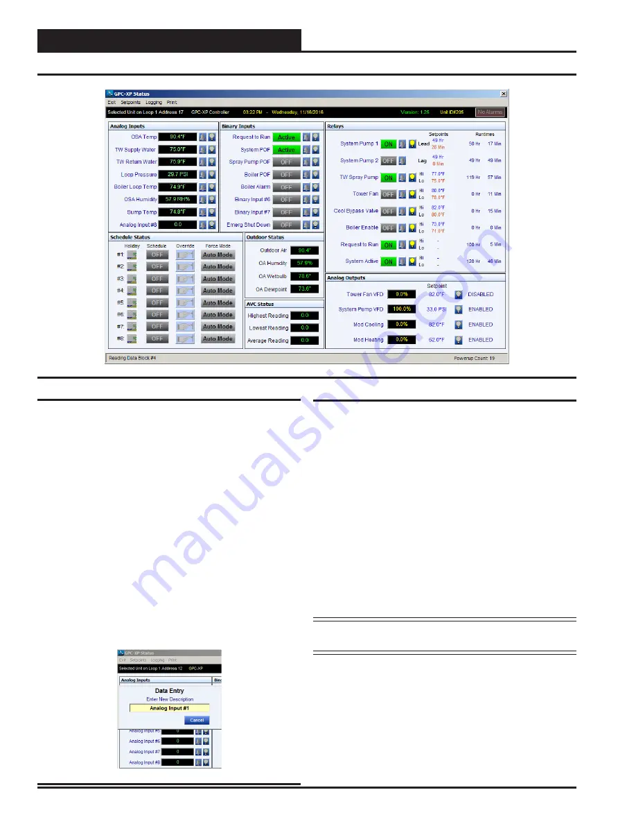
Figure 8: GPC-XP Status Screen
Status Screen
Figure 8
shows a typical GPC-XP status screen after being configured
for use as a Central Plant Controller. To create a description for an
input “double click” on any of the existing descriptions to change to an
appropriate description for the Central Plant Controller input or output
you selected. A popup window will appear allowing you to change the
description as needed. See
Figure 9
.
For Analog Input #1 change the description to “Outdoor Air Tempera-
ture” and hit the “Enter” key as shown above.
If you have a Supply Water Temperature sensor enter it as the Analog
Input #2 with its description. If you have a Return Water Temperature
sensor enter it as Analog Input #3 with its description. If you have a Dif-
ferential Pressure Sensor enter it as the Analog Input #4 with its descrip-
tion. Enter a description for any other input sensors you have in the rest
of the remaining input description areas. At the very minimum you will
need to create Analog Inputs for OA Temperature and Return or Supply
Water Temperature in order to control the equipment on your Central
Plant system. Other inputs may be required for your specific project.
NOTE:
Be sure to hit “Enter” after each description is changed
or the change will not occur.
The configuration and setpoints can also be reached from the ‘Status
Screen” by double clicking the data display box to the right of the de-
scription area. Once configured and the system is communicating this
box will contain the current value of the input you have entered. “Double
click” the data box next to the “Outdoor Air Temperature” description
to open the configuration and setpoint screen for AIN1.
General
Using the GPC-XP as a Water Source Heat Pump Loop Controller
requires that it be configured for your application. The information that
follows will show you how to configure a GPC-XP controller for a typical
Central Plant Loop Controller application. If you want to start with the
typical setpoints we have used in this manual as a starting point you can
enter them by hand or you can download and install a pre-configured
setup screen and setpoints used in these examples if you wish.
To download the typical WSHP Loop controller setup screen go to the
Auto-Zone 2 Controls web site at www.az2controls.com. Click on the
software tab at the top of the web page. Scroll to the bottom of the web
page and find the listing “
GPC-XP Used For WSHP Loop Control-
ler – Setup File
” and click on the “click here” text to download the
self extracting file.
Once you have downloaded the file go to its location and “double click”
on the file and then unzip it to the directory listed in the “unzip to win
-
dow”. You can now select the “Restore To File” tab located under the
“Setpoints” tab at the top of the GPC-XP Status screen to select the file
“WSHP-Typ-Setpoints.SPT” and it will populate the GPC-XP status
screen with all the typical setpoints and descriptions like the screen
shown in
Figure 8
. You can now change or delete the setpoints or con-
figurations as desired to match your requirements.
Figure 9: Entering Input & Output Descriptions
Configuration
14
WSHP Loop Controller
GPC-XP Guide


