background image

Basic Operations

 - 4.1 

Outline of Daily Operations


11 


44.


Basic Operations 

4.1.


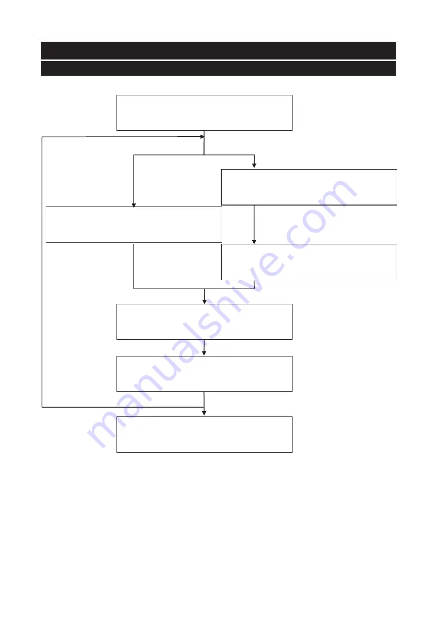
Outline of Daily Operations 


Turning on 

Refer to "

4.2.1. Turning the Power ON

Selection of product 

Refer to "

4.6. Target Product

Registration of product 

Refer to "

4.7.1. Registering the Product

Change of user management   

Refer to "

4.4.2. Login

If inspecting a new product 

If inspecting a preset product 

"Supervisor" level or higher is 

required 

Inspection 

Refer to "

4.10. Starting and Stopping the 

IInspection

Results of the inspection 

Refer to "

4.11. History Management

Turning the Power OFF 

Refer to "

4.2.2. Turning the Power OFF

If changing the product 

Содержание AD-4971

Страница 1: ...1WMPD4002757B ...

Страница 2: ...ribed or translated into any language in any form by any means without the written permission of A D Company Limited The contents of this manual and the specifications of the instrument covered by this manual are subject to change for improvement without any notice and obligation on the part of the manufacturer ...

Страница 3: ... Home Screen 13 4 3 1 Inspection Screen 13 4 3 2 Bar Graph Screen 14 4 3 3 Lissajous Graph Screen 15 4 3 4 Inspection Settings Screen 15 4 4 User Management 16 4 4 1 UserAccess Control 16 4 4 2 Login 16 4 4 3 Logout 17 4 5 Management of User List 18 4 5 1 Registering a New User 18 4 5 2 Changing User Information 19 4 5 3 Deleting a User 20 4 6 Target Product 21 4 7 Product Registration 21 4 7 1 Re...

Страница 4: ...oduct Settings Screen Product Settings Tab 40 7 2 1 FAIL Limit Settings Screen 40 7 2 2 Inspection Phase Settings Screen Phase Tab 42 7 2 3 Inspection Phase Settings Screen Phase Tracking Tab 42 7 2 4 FAIL Behavior Settings Screen 43 7 2 5 DO Map Settings Screen 44 7 2 6 DO Behavior Settings Screen 45 7 2 7 Calibration Settings Screen 46 7 3 Settings Screen Common Settings Tab 46 7 3 1 DI Settings...

Страница 5: ...ck after Use Inspection 66 10 1 3 Periodical Check and Maintenance 66 10 2 Cleaning 67 10 2 1 Light Dirt 67 10 2 2 Heavy Dirt 67 10 3 Maintenance of the Conveyor Belt 68 10 3 1 Removing the Conveyor Belt 68 10 3 2 Attaching the Conveyor Belt 69 10 3 3 Conveyor Belt Tracking and TensionAdjustment 69 11 Maintenance 70 11 1 The system file 70 11 1 1 Saving the System File 70 11 1 2 Restoring the Syst...

Страница 6: ...4 13 3 Phase Tracking 77 13 4 Rotate Direction 78 ...

Страница 7: ...ofand Dustproof TheAD 4971 is equipped with a waterproof and dustproof frame in compliance with IP65 Conveyor Belt In comparison with timing belt drives the gear driven conveyor belt mechanism allows for easy maintenance removal attachment and tracking and tension adjustments Functions TheAD 4971 can divide products into ten groups and register a maximum of 100 products for each group a total of 1...

Страница 8: ...Install theAD 4971 on a solid surface away from sources of vibration Install theAD 4971 in an area where it is not exposed to direct sunlight Install theAD 4971 in an area where it is not subject to drafts from windows electric fans or air conditioners Be sure to install theAD 4971 on a level surface Grounding Be sure to ground theAD 4971 to avoid electrical shock fire or malfunction Precautions f...

Страница 9: ...etects the product using the photo electric sensor and reflector 3 Conveyor belt Conveys the product 4 I O box Receives and processes the inspection signal controls theAD 4971 The power switch is located on the front panel of the I O box 5 Sensor head Outputs the inspection signal from the sensor unit which detects metal in the passing product 6 Power switch Turns on theAD 4971 when rotating the s...

Страница 10: ... USB terminal cover Awaterproof cover for a USB terminal is attached 2 3 I O Box Input Output Module 1 2 3 4 5 6 Fig 3 3 I I OBox No Name Description 1 Mainsterminal Connectsthepowerwirestoterminals Upper Live Middle Neutral Lower Power ground earth 2 Serialinterface Connectstheserialcommunicationwires 3 Modbusinterface ConnectstheModbuscommunicationwires 4 PEsensor ConnectsthePEsensorwires 5 LANc...

Страница 11: ...enOperations 3 2 Input Dialog Box 3 2 1 Numerical Input Dialog Box Password Input Dialog Box When a numerical value is required the numerical input dialog box is displayed When a password is required for a user login or user registration the password input dialog box is displayed Input is the same as the numerical input dialog box The inputted characters are displayed using so secrecy can be maint...

Страница 12: ...hes Roman alphabet characters and numerical characters 2 Caps button Switches lowercase and uppercase 3 Cursor button Moves the cursor 4 SP button Selects a symbol 3 2 3 Drop Down List Dialog Box When an item selection is required the drop down list dialog box is displayed 1 2 3 Fig 9 9 D DropDownListDialogBox No Name Description 1 Item The options to select 2 OK button For selecting an item 3 Can...

Страница 13: ...stration of product Refer to 4 7 1 Registering the Product Change of user management Refer to 4 4 2 Login If inspecting a new product If inspecting a preset product Supervisor level or higher is required Inspection Refer to 4 10 Starting and Stopping the I Inspection Results of theinspection Refer to 4 11 History Management Turning the Power OFF Refer to 4 2 2 Turning the Power OFF If changing the...

Страница 14: ...er switch 90 degrees clockwise to turn on the AD 4971 Fig 1 10 T Turningon 4 2 2 Turning the Power OFF The power switch is located on the front of the I O box Rotate the power switch 90 degrees counterclockwise to turn off theAD 4971 Fig 1 11 T Turningoff Cautions The same operation is performed for an emergency stop When an emergency stop has been performed turn on theAD 4971 again only after the...

Страница 15: ...1 1 2 3 4 Fig 1 12 I InspectionScreens No Name Description 1 No Inspected product number 2 Login user Current login user name 3 Count Thetotalcount thePASScount theFAILcount theFAILrate 4 Product information The inspected product name and product code 5 Product image Inspected product image 6 Calibration icon Calibration screen is displayed 7 Product icon Product selection screen is displayed 8 Hi...

Страница 16: ...raph The product effect of type Q 3 Pbargraph The product effect of type P 4 Peak ratio Peak ratio of the product effect in relation to the sensitivity setting value Table1 1 T TypesofProductEffect Name Description I The In phase Q The Quadrature phase P The minimum phase of the product effect Information Refer to 7 2 2 Inspection Phase Settings Screen Phase Tab 2 1 3 Fig 1 14 B BarGraph No Name D...

Страница 17: ...ndard inspections Fig 1 15 L LissajousGraphScreens 4 3 4 Inspection Settings Screen This screen displays the part of the Inspection settings The inspection result Good PASS Defective FAIL is displayed in the right upper corner of the screen Touch the Display icon to switch to the Inspection screen 2 3 1 Fig 1 16 I Inspection Settings Screen No Name Description 1 Beltspeed ValueofBeltspeedforInspec...

Страница 18: ...lable depend on the user level Assign an appropriate user level to avoid an inadvertent operation prohibited operation and use theAD 4971 safely When the power is turned on the default user level is Operator Table2 2 O OperationAuthority User Level OperationAuthority Inspection Start Stop History Product Selection Product Registration SystemSettings User Settings Administrator Fulloperation ۑ ۑ ۑ ...

Страница 19: ...rator 4 Edit button The button moves the user to the Edit screen Only an Administrator can edit user data 5 User name input field Input a user name 6 Password input field Input the password 7 Login button Touch the button to enter the program 4 4 4 3 Logout If you use a new user level exit from the program 1 Touchthe User iconinthe Home screen todisplay the Logout screen 2 Touch the Logout button ...

Страница 20: ... registered changed or deleted 4 5 1 Registering a New User Note The user list cannot register a new user name which is the same as an existing one However theAD 4971 distinguishes upper and lower case characters so they can be used separately 1 Touch the Edit icon to display the Edit screen 2 Touch the Registration icon to display the User registration screen Input a user name number of character...

Страница 21: ...on the Login screen to display the Edit screen 2 Touch the Edit icon to display the Selecting user screen 3 Select a user to change the user information from the list If the Re selection icon is touched the Selecting user screen is displayed 4 Input a revised password of four digits Select user level from Administrator QualityManager and Supervisor 5 Touch the Change buttonto display the Change di...

Страница 22: ...matically 1 Touch the Edit icon on the Login screen to display the Edit screen 2 Touch the Delete icon to display the Deleting user screen 2 1 Fig 2 21 D DeletingUserScreen No Name Description 1 Delete button Aspecified user is deleted 2 Delete all button All users without Admin user login are deleted Deleting a User 1 Select a user from the list 2 Touch the Delete buttonto display the Delete dial...

Страница 23: ...No Name Description 1 Group number input field Input group number number of product list Range 1 to 10 2 No input field Input product number Range 1 to 100 3 Reading icon The data of the specified number is inputted 4 Editing icon The screen is displayed to edit the product data 4 7 Product Registration TheAD 4971 can use 10 product lists groups that can register a maximum of 100 products items ea...

Страница 24: ...Length 0 to 20 4 Touch the Product setting screen Tab to display the menu 5 Adjust sensitivity and set necessary settings Fig 2 24 P ProductSelectionScreen Information Refer to 4 8 Sensitivity Adjustment and Inspection Mode Refer to 7 Reference Table of Screens and Menu Items 1 2 3 4 5 Fig 2 25 P ProductEditScreen Tab No Name Description 1 Product name input field Input a product name Length 0 to ...

Страница 25: ... C CopyingtheProductData 1 Display the Product edit screen 2 Touch the Copy buttonto display the Copy dialog box and touch the Yes button 3 Confirm that the product list has been copied Fig 2 27 P ProductEditScreen Tab 4 7 3 Deleting the Product Data This function can delete the product data and reset the registration of the product 1 Display the Product edit screen 2 Touch the Delete buttonto dis...

Страница 26: ...lash drive to the display module of theAD 4971 3 Touch the Image buttonto display the Image selection screen When touching a folder the folder is opened The Return icon returns to the screen of the previous menu The Cancel icon completes the image selection The Thumbnail icon displays a thumbnail layout of image files The List icon displays a list of image files 4 Touch an image file to select it ...

Страница 27: ...4971 Stop theAD 4971 immediately if the gear cover is removed during operation Stop theAD 4971 immediately if the electric motor generates excessive heat or produces unusual sounds Avoid any shock impact or excessive load to the conveyor belt during operation Caution It may not be possible to achieve stable inspections immediately after operation starts due to noise generated by the machine starti...

Страница 28: ...n as it cannot be changed during inspection Take care to ensure the correct belt speed and product length are input as these cannot be changed during the inspection If the product length is incorrect it may cause errors in inspection and operation Mode I Mode II Mode III Mode IV Mode I III Mode II IV Fig 2 29 S SensitivityAdjustmentScreens ...

Страница 29: ...s excessive heat or produces unusual sounds Avoid any shock impact or excessive load to the conveyor belt during operation Caution It may not be possible to achieve stable inspections immediately after operation starts due to noise generated by the machine starting up 1 Touch the Calibration icon in the Home screen The Calibration screen is displayed 2 Check the settings and touch the Start to Cal...

Страница 30: ...is removed during operation Stop theAD 4971 immediately if the electric motor generates excessive heat or produces unusual sounds Avoid any shock impact or excessive load to the conveyor belt during operation Caution It may not be possible to achieve stable inspections immediately after operation starts due to noise generated by the machine starting up 1 Confirm that nothing is placed on the conve...

Страница 31: ... Quality Manager or higher usertouchesthe Clear icon alloftheinspectionresults aredeleted Fig 3 31 I InspectionResultsScreen Theinspectionresultsareswitchedusingthe Up and Down icons Touch the Left icon to display the Error history screen Touch the Right icon to display the Inspection history screen No Name Description 1 Start time Time that the inspection is started 2 Stop time Time that the insp...

Страница 32: ...to store the calibration results When connecting the printer touch the Print icon to print the calibration results When inputting the Display No the calibration result is displayed Ifthe Quality Manager or higher usertouchesthe Clear icon allofthecalibration resultsaredeleted Fig 3 33 C CalibrationResultsScreen Thecalibrationresultsareswitchedusingthe Up and Down icons Touch the Left icon to displ...

Страница 33: ... No Product number when the settings were changed 4 Item Item when the settings were changed 5 Details Details when the settings were changed 4 11 5 Error History Screen The screen can display a maximum of the last 100 items Touch the Left icon to display the Operation history screen Touch the Right icon to display the Inspection results screen Fig 3 35 E ErrorHistoryScreen No Name Description 1 T...

Страница 34: ...nection is complete the USB icon is displayed on the screen 3 If the icon is not displayed within 10 seconds remove and re connect it again It may need some time to display the icon because of total capacity and used capacity Fig 3 36 T TerminalforUSBFlashDrive 23 mm 70 mm USB Fig 3 37 U USBSize Fig 3 38 U USBFlashDriveConnection 5 1 2 Removing a USB Flash Drive 1 Touch and hold the USB icon on th...

Страница 35: ...to display the PDF dialog box and touch the YES button Fig 4 40 I InspectionResults Directory Root directory of the USB drive File name Result_Detect_ Start Time pdf File name Result_Calibr_ Start Time pdf Inspection Results When the beginning of the inspection is 08 09 201414 37 25 the filename is Result_Detect_20140908143725 pdf If many defective products are recorded multiple pages are used The...

Страница 36: ... Setting screen System tab to display the USB setting screen Set the Export inspection history to Enable 4 When the inspection is started the inspection history is stored in USB memory When the settings are changed the operation history is stored in USB memory Fig 4 43 U USBSettingsScreen Directory Root directory of the USB drive File name First Time of Detection csv File name Working_History_Save...

Страница 37: ...as deleted data cannot be restored User level of QualityManager or higher is required to format the USB memory 1 Connect the USB flash drive to the connector on the display module 2 Touchthe Setting iconinthe Home screen to displaythe Setting screen 3 Touch the USB setting buttonin the Setting screen System tab to display the USB setting screen 4 Touch the Format USB buttonto display the USB forma...

Страница 38: ...1 Fig 4 47 P PrinterScreen USB 6 1 2 Connecting a Printer to LAN Port 1 Connect the LAN cable of the printer to the LAN port of the I O box 2 Touch the Printer buttonin the Setting screen System tab to display the Printer screen 3 Select LAN on the Printer screen Input the IP address of the LAN printer 4 Restart theAD 4971 Fig 4 48 P PrinterScreen LAN 6 2 Printing Results and History 6 2 1 Printin...

Страница 39: ... Phase I Phase Q Phase P Phase tracking tab Page42 Phase tracking Reset phase tracking Init phasemode NumberofInit phase Value of phase tracking FAILbehavior screen Page43 Consecutive FAILstop Consecutive FAILcount Stop belt mode Stop belt distance Delaytimeofdetection DO map screen Page44 PASS FAIL1 FAIL2 FAIL3 FAIL4 Cal PASS Cal FAIL1 Cal FAIL2 Cal FAIL3 Cal FAIL4 Error alarm FAILstop Inspecting...

Страница 40: ...ion time of PE sensor PE sensor error time Function 3 tab Page49 Rotation direction Rotation direction of Rejecter Error of Rejecter Belt speed adjustment screen Page50 BeltSpeed Metal Detector Low Speed Metal Detector High Speed Rejecter Low Speed Rejecter High Speed Counter settings screen Page51 Count reset at sensitivity adjustment Count overflow mode Count mode FAILcount mode Communication se...

Страница 41: ...actory default USB memory settings screen Page56 Total capacity Free space Export inspection history Export operation history Language settings screen Page57 Language Software version screen Page57 Software version 7 7 1 Product Settings Screen Product Edit Tab 1 2 3 4 5 Fig 5 50 P ProductSettingsScreen ProductEditTab No Name Scope Description 1 Productname 0 to 15 characters Registerstheproductna...

Страница 42: ...ys the FAIL behavior settings screen 5 DO map settings button Displays the DO map settings screen 6 DO behavior settings button Displays the DO behavior settings screen 7 Calibration settings button Displays the Calibration settings screen 7 2 1 FAIL Limit Settings Screen 1 4 2 3 Fig 5 52 F FAILLimitScreen No Name Scope Description 1 FAILlimitI 3 0 0 1to99 9 Setsamagnificationofdetectionlevelforth...

Страница 43: ...nderLimit The under limit is used to detect a product passing the sensor head The figure on the right depicts passing products with the value of the under limit set to 0 5 The value of sensitivity setting is 1 0 When the detection level exceeds the product effect of the inspection it is recognized that the product has passed the sensor head At the same time the product is judged as either good or ...

Страница 44: ...ld be changed by the person authorized for managing theAD 4971 7 2 3 Inspection Phase Settings Screen Phase Tracking Tab 3 1 5 2 4 Fig 5 54 I InspectionPhaseScreen PhaseTrackingTab No Name Scope Description 1 Phasetracking Disable Enable Theinspectionphaseisautomaticallytracedaccordingtothechangeofthe productphase 2 Resetphase tracking None Atinspectionstop Selectsthetimetoresetthephasetrackingwhe...

Страница 45: ...te At the end of belt Thestopbehaviorwhendetectingdefectiveproducts SetthebeltstopfunctionintheDObehavior 4 Stop belt distance 480 0 to 9999 mm Whenusingthebeltendstopfunction setthedistanceafterpassing thePEsensor ThismodecannotbeusedifthePEsensorisnotused 5 Delaytimeof detection 1 00 0 00to9 99sec For the case of the detection without PE sensor set the time until next detection becoming effectiv...

Страница 46: ... a DO signal is outputted FAIL 3 means that two defective products are detected 1 5 FAIL4 Disable Enable When detecting a defective product during the inspection a DO signal is outputted FAIL 4 means the failure of peripherals No Name Scope Description 2 1 CalPass Disable Enable When a good product is detected during calibration a DO signal is outputted 2 2 CalFAIL1 Disable Enable When a defective...

Страница 47: ...is outputted 4 3 Calibration Disable Enable When calibratingAD 4971 a DO signal is outputted 4 4 Settingsensitivity Disable Enable When adjusting the sensitivity a DO signal is outputted 4 5 CPUrun Disable Enable When the software is executing a DO signal is outputted N Note DO settings cannot be outputted solely by themselves Set the DO settings with 7 2 6 DO Behavior Settings Screen 7 2 6 DO Beh...

Страница 48: ...top Selects a treatment at calibration error 7 3 Settings Screen Common Settings Tab 1 3 5 2 4 Fig 5 59 S SettingsScreen CommonSettings T Tab No Name Description 1 DI settings button Displays the DI settings screen including the Configuration tab and DI behavior tab 2 Function settings button Displays the Function settings screen including the Function 1 and Function 2 tabs and Belt speed adjustme...

Страница 49: ...receiving the DI signal an error state is canceled Reset count When receiving the DI signal the total count is reset Peripheral FAIL When receiving the DI signal theAD 4971 treats it as a peripheral FAIL Forced DO 1 When receiving the DI signal it is outputted to the DO 1 Forced DO 2 When receiving the DI signal it is outputted to the DO 2 Forced DO 3 When receiving the DI signal it is outputted t...

Страница 50: ...onnected to Contact A makes contact with ON the DI signal can be received Negative When the device connected to Contact B makes contact with ON the DI signal can be received Note The DI behavior settings can set to DI 1 DI 2 DI 3 and DI 4 7 3 3 Function Settings Screen Function 1 Tab 3 4 2 1 Fig 6 62 F FunctionSettingsScreen Function1 Tab No Name Scope Description 1 FAIL1 OFF ON Judgment of FAIL1 ...

Страница 51: ... PE sensor 0 00 0to9 99sec The time to prevent chattering 4 PE sensor error time 30 0 0 0to99 9sec The time to recognize an error If0isset noerrorswillberecognized 7 3 5 Function Settings Screen Function 3 Tab 2 3 1 4 Fig 6 64 F FunctionSettingsScreen Function3 Tab No Name Scope Description 1 Rotation direction MotorCW MotorCCW Rotation direction of the motor 2 Rejector rotation direction MotorCCW...

Страница 52: ... min The belt speed of the rejecter can be inputted 5 Rejecter Highspeed 50 0 10 0to60 0m min The belt speed of the rejecter can be inputted Note Atachometer is necessary to adjust the speed This belt speed adjustment cannot be used during the inspection Perform the belt speed adjustment of the rejecter when assembling the metal detector and rejecter Perform the belt speed adjustment in order from...

Страница 53: ...ehavior can be selected when the counter is in overflow 3 Count mode Totalcount Eachinspection Select what to count from Total number PASS number and FAILnumber options on the Inspection screen Total count The total count of the products is displayed Each inspection The count of the current product is displayed At the next product the current counter is reset 4 FAILcount mode FAIL1 FAIL2 FAIL3 FAI...

Страница 54: ...nication 4 Data bits 7 bits 8 bits Data length of the serial communication 5 Stop bits 1 bits 2 bits The stop bits of the serial communication 7 3 9 Connection Settings Screen Modbus Interface Tab 3 1 5 2 4 Fig 6 68 C ConnectionSettingsScreen ModbusInterfaceTab No Name Scope Description 1 Modbus mode OFF Modbus RTU Modbus TCP The Modbus communication mode 2 Slave address 1 1 to 247 Address of the ...

Страница 55: ...m Settings Tab 1 3 5 7 2 4 6 8 Fig 7 70 S SettingsScreen SystemSettingsTab No Name Description 1 Date Time settings button Displays the Date Time settings screen 2 LCD settings screen button Displays the LCD settings screen 3 LAN settings button Displays the LAN settings screen 4 Speaker settings button Displays the Speaker settings screen buzzer 5 Backup Restore button Displays the Backup Restore...

Страница 56: ...ply button New date and time are applied in theAD 4971 Note It may take several seconds when applying new date and time in theAD 4971 Please be aware of this time delay 7 4 2 LCD Settings Screen 1 2 Fig 7 72 L LCDSettingsScreen No Name Scope Description 1 Sleep timer 0 0to99min When the timer exceeds the set value the operation panel of the display module enters sleep mode If 0 is set the panel do...

Страница 57: ... mask of theAD 4971 3 Default gateway 0 0 0 0 The default gateway of theAD 4971 Note When you use new LAN settings please restart theAD 4971 7 4 4 Speaker Settings Screen 2 1 3 Fig 7 74 S SpeakerSettingsScreen No Name Scope Description 1 Volume Vol 0 Vol 1 Vol 2 Vol 3 Vol 4 Vol 5 The volume of the speaker on the display module 2 FAILbuzzer OFF ON Sounds when detecting a defective product 3 Start S...

Страница 58: ...tory default switch All settings are reset to the factory settings Refer to 1 11 1 3 R Resetting to Factory Settings 7 4 6 USB Memory Settings Screen 1 2 3 4 5 Fig 7 76 U USBMemorySettingsScreen No Name Scope Description 1 Total capacity 0 0MB The capacity of the USB memory 2 Free space 0 0MB The spare capacity of the USB memory 3 Export inspection history Disable Enable The inspection history is ...

Страница 59: ...l Note The language settings screen is always displayed in English 7 4 8 Software Version Screen 1 Fig 7 78 S SoftwareVersionScreen No Name Scope Description 1 Software version The current software version is displayed Note The software is subject to change for improvement without any notice or obligation on the part of the manufacturer The software version does not indicate compatibility between ...

Страница 60: ...n registered a new registration is performed and the settings are read 8 1 RTU Connection for Modbus 1 Display the Communication settings screen Modbus tab Select Modbus RTU for Modbus mode 2 Restart theAD 4971 after setting Modbus After restarting the settings will become effective 3 Input a slave address 4 Display the Communication settings screen Serial tab Modbus RTU has 8 data bits 5 Connect ...

Страница 61: ...ster 3 Read only word data Used to read communication settings and count data Holding register 4 Read and write word data Used to change the settings and read each product setting 8 4 Address for Modbus Table8 8 O OutputCoilAddress Table9 9 I InputStatusAddress Address Name Address Name 00001 DI 1 10001 DI 1 00002 DI 2 10002 DI 2 00003 DI 3 10003 DI 3 00004 DI 4 10004 DI 4 00005 DI 5 10033 DI Stat...

Страница 62: ... detector 0 to 255 30032 High speed of rejecter 10 0 to 60 0 30011 Default gateway 3 of the metal detector 0 to 255 30033 Total count of PASS 0 to 9999999 30012 Default gateway 4 of the metal detector 0 to 255 30035 Total count of FAIL1 0 to 9999999 30013 Default printer 0 to 1 30037 Total count of FAIL2 0 to 9999999 30014 Printer IP address 1 0 to 255 30039 Total count of FAIL3 0 to 9999999 30015...

Страница 63: ...ring prevention time 0 00 to 9 99 40081 DO 7 Holding time 0 00 to 99 99 40040 DI 4 Chattering prevention time 0 00 to 9 99 40082 DO 8 Holding time 0 00 to 99 99 40041 DI 1 Delay time 0 00 to 99 99 40083 DO 1 Polarity 0 to 1 40042 DI 2 Delay time 0 00 to 99 99 40084 DO 2 Polarity 0 to 1 40043 DI 3 Delay time 0 00 to 99 99 40085 DO 3 Polarity 0 to 1 40044 DI 4 Delay time 0 00 to 99 99 40086 DO 4 Pol...

Страница 64: ... 1 40106 Phase P 0 5 to 180 0 40122 Distance to stop 1 to1000 40107 Phase tracking ON OFF 0 to 1 40123 Delaytimeofdetection㻌 0 00 to 9 99 40108 Phase tracking reset ON OFF 0 to 1 40124 Init phasemode㻌 0 to 2 40109 Calibration PASS count 0 to 10 40125 Numberofinit phase㻌 1 to 10 40110 Calibration FAILcount 0 to 10 40126 Numberofphaseadjustment㻌 1 to 10 40111 Calibration error 0 to 1 40127 Rejector ...

Страница 65: ...y stop output signal INPUT TM4 INPUT 1 DI 1 General purpose input signal 1 INPUT 2 DI 2 General purpose input signal 2 INPUT 3 DI 3 General purpose input signal 3 INPUT 4 DI4 General purpose input signal 4 INPUT COM IN COM General purpose input signal COM TM3 GND GND 24 V ground 24V 24V 24 V power source GND GND 24 V ground 24V 24V 24 V power source GND GND 24 V ground OUTPUT TM2 OUTPUT 5 DO 5 Gen...

Страница 66: ...3 GND 24V GND 24V GND OUTPUT TM2 OUT2 COM DO8 DO7 DO6 DO5 OUTPUT TM1 OUT1 COM DO4 DO3 DO2 DO1 Fig 8 81 L LayoutofGeneral P PurposeInput O OutputTerminals 䯲External power supply 24 V 250 mA Maximum 9 2 Circuits of General Purpose I O Terminals 9 2 1 Contact Input Terminals 4 3 1 2 2K 1 2W 4 3 1 2 4 3 1 2 4 3 1 2 2K 1 2W 2K 1 2W 2K 1 2W DI1 DI2 DI3 DI4 IN COM Fig 8 82 C CircuitofContactInputTerminal...

Страница 67: ... DO4 OUT1 COM 1 2 DO5 1 2 1 2 1 2 4 3 4 3 4 3 4 3 DO6 DO7 DO8 OUT2 COM Fig 8 83 C CircuitofOutputRelayTerminals 60V 500mA Maximum 9 2 3 Input and Output Terminals for Emergency Stop 4 3 1 2 2K 1 2W 4 3 1 2 1 2 4 3 2K 1 2W EMG IN1 EMG IN2 EMG OUT EMG COM EMG OUT Fig 8 84 C CircuitofInput O OutputTerminalsforEmergencyStop 䯲Thiscircuitisreservedfor futureuse ...

Страница 68: ...ecter is used check the behavior of good and defective product selection If the rejecter cannot select correctly adjust the settings again and the configuration of input and output 10 1 2 Check after Use Inspection Please be sure to make the following check after the inspection Check the sensitivity of the detection Confirm detection is functioning normally performing adjustment for good and defec...

Страница 69: ...ss Check the conveyor belt Remove the conveyor belt check for fraying warping abrasion cracks or any other deformities Note Select the appropriate cleaning depending on the packaging and the product 10 2 2 Heavy Dirt On a regular basis remove the conveyor belt and the sliding plate Two tension roller a drive roller and slave roller Openingofthesensorhead Especiallytheunderside Backsideoftheconveyo...

Страница 70: ...drop the roller or belt 10 3 1 Removing the Conveyor Belt 1 TurnoffthepowertotheAD 4971 2 Removethefourdrawlatches 3 Removethegearcase 4 Liftupthedriverollersideoftheconveyorbed slidingplate 5 Liftuptheslaverollersideoftheconveyorbed Moveitto theside 6 Removetheslaveroller 7 Removethedriveroller takingcaresoas nottogripthe gear 8 Removetheconveyorbeltandconveyorbedfrom the sensorheadinthedirection...

Страница 71: ...Screws Flat face 10 3 3 Conveyor Belt Tracking and Tension Adjustment CAUTION When the tension of the belt unnecessarily increases the load on the motor increases and it may cause a failure or accident Reversing the rotation direction of the belt may cause meandering Loosen the screw on the side on which the belt is shifting Or fasten the screw on the other side If the screws are loosened too much...

Страница 72: ...e Backup dialog box and touch the YES button Fig 8 85 B Backup RestoreScreen Directory Drive name ad4971_backup year month date hour minute _CK 11 1 2 Restoring the System File Note TheAD 4971 only supports USB memory using FAT32 format TheAD 4971 cannot correctly display a Japanese directory name or filename in the Product selection screen 1 Touch the Backup Restore buttonin the Setting screen Sy...

Страница 73: ...ystem files before this reset Amalfunction or error may occur due to the loss of the settings when resetting theAD 4971 1 Touch the Backup Restore buttonin the Settings screen System tab to display the Backup Restore screen 2 Connect the USB flash drive to the connector on the display module 3 Touch the Initialization button to display the Factory default dialog box and touch the YES button 4 When...

Страница 74: ...r Messages TheAD 4971 will display an error message when an error occurs Whenanerrormessageisdisplayed followthesuggestedresponseofthetablebelow Table1 14 E ErrorMessages Error Code Description Cause Suggested Response 101001 Failure to initialize system Failure to read system file when turning on Refer to 11 3 Treatment of an Error at System Initialization 102001 Failure to write to FRAM Contact ...

Страница 75: ... dealer 104006 Speed Rejector If you have any questions please contact your dealer 1 11 3 Treatment of an Error at System Initialization 1 Touch the OK button to close the dialog box 2 Touch the User icon in the Home screen to display the Login screen User level QualityManager or higher is required 3 Touchthe Setting iconinthe Home screen todisplaythe Setting screen 4 Touch the Backup Restore butt...

Страница 76: ...on 7 inch WVGATFT color LCD touch panel Maximum number of items to be stored 1000 items including product data and image Detection method Metal detection with electromagnetic induction EMI and single frequency 300 kHz Stabilization time 2 hours Metal detection output Beltstop automaticrejecter warninglight communicationport Communication TCP IP PostScript Printer Modbus RS 232C to connect toAD 496...

Страница 77: ...12 Specifications 12 2 Dimensions 75 1 12 2 Dimensions ...

Страница 78: ...oninthe Productsetting screen Productsettingstab todisplaythe DOMap screen Touch the Stop check box and switch to the check mark Fig 9 90 S Stop I Immediately 13 1 2 Stop at the End of Belt Comveyor StopattheendofbeltconveyorwhenFAIL1isdetected isgivenasanexample 1 Touchthe FAILbehavior buttoninthe Productsetting screen Productsettingstab todisplaythe FAILbehavior screen Select At the end of belt ...

Страница 79: ...ation feed the product without testpiece for phase tracking 3 Start normal calibration Fig 9 92 P PhaseTracking i in C Calibration 13 3 Phase Tracking 4 Touchthe Phase buttoninthe Productsetting screen Productsettingstab todisplaythe Phasesettings screen Phasetrackingtab Select Enable for Phase tracking Select an arbitrary setting for Resetphasetracking Select an arbitrary setting for Init phasemo...

Страница 80: ...ction buttoninthe Setting screen Commonsettingstab todisplaythe Functionsetting screen Function3tab Select Rotate CCW for Rejectorrotationdirection 2 ChangethepositionofPEsensor 3 Removetheconveyorbeltandattachittomatchtherotationdirection includedatthebacksurface 4 Tracktheconveyorbeltandadjusttension Fig 9 94 R RotateDirection ...

Страница 81: ...79 MEMO ...

Страница 82: ...80 MEMO ...

Страница 83: ......

Страница 84: ...reet Thebarton South Australia 5031 AUSTRALIA Telephone 61 8 8301 8100 Fax 61 8 8352 7409 A D KOREA Limited 䚐ạ㜄㢨U㜈U O㨰P 㤎䔏 㔲G 㡗 䙂ῂG ῃ㩲 㦋 ZZGO㡂㦮 PG ⰾ䞮䌚ア G _X 㤆䘎 䢎 X WT 817 Manhattan Bldg 33 Gukjegeumyung ro 6 gil Yeongdeungpo gu Seoul 150 749 Korea 㩚䢪 82 2 780 4101 䕿㓺 82 2 782 4280 OOO A D RUS OOO ɗɃ ɷɧɞ Ⱦɂ Ɋɍɋ 121357 Ɋɨɫɫɢɣɫɤɚɹ Ɏɟɞɟɪɚɰɢɹ ɝ Ɇɨɫɤɜɚ ɭɥ ȼɟɪɟɣɫɤɚɹ ɞɨɦ 17 Business Center Vereyskaya Plaz...

Отзывы: