38
NO
.
INDICATION
LIKELY REASON
SOLUTION
8
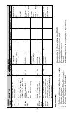
Gas flows through the
XFM, but LCD Display
reading and the output
voltage 0-5 Vdc signal
do not respond to flow.
The gas flow is too low
for particular model of
XFM.
Check maximum flow range on transducer’s
front panel and make required flow
adjustment.
XFM 17 models: RFE is
not connected properly
to the inlet fitting.
Unscrew the inlet compression fitting of the
meter and reinstall RFE (see section 6.2.2).
NOTE: Calibration accuracy can be affected.
Sensor or PC board is
defective.
Return XFM to factory for repair.
9
Gas does not flow
through the XFM with
inlet pressure applied
to the inlet fitting. LCD
Display reading and
output voltage 0-5 Vdc
signal show zero flow.
Filter screen obstructed
at inlet.
Flush clean or disassemble to remove
impediments or replace the filter screen
(see section 6.2).
NOTE: Calibration accuracy can be affected.
10 Gas flows through the
XFM, output voltage 0-
5 Vdc signal does not
respond to flow
(reading near 1mV).
Direction of the gas
flow is reversed.
Check the direction of gas flow as indicated
by the arrow on the front of the meter and
make required reconnection in the
installation.
XFM is connected in the
installation with back
pressure conditions and
gas leak exist in the
system.
Locate and correct gas leak in the system. If
XFM has internal leak return it to factory for
repair.
11 The Status LED
indicator is rapidly
flashing with AMBER
color on /off.
Sensor temperature is
too low.
Make sure the ambient and gas
temperatures are within specified range
(above 5
°
C)
12 The Status LED indica
tor is rapidly flashing
with RED color on /off.
Sensor temperature is
too high.
Make sure the ambient and gas
temperatures are within specified range
(below 50
°
C)
13 The Status LED
indicator is rapidly
flashing with RED and
AMBER colors.
MCU temperature is too
high (overload).
Disconnect power from the XFM. Make sure
the ambient temperature is within specified
range (below 50
°
C). Let the device cool
down for at least 15 minutes. Apply power
to the XFM and check Status LED indication.
If overload condition will be indicated again
the unit has to be returned to the factory for
repair.
14 The Status LED
indicator is constantly
on with the RED light.
Fatal Error (EEPROM
or Auto Zero error).
Cycle the power on the XFM. If Status LED
still constantly on with RED light, wait 6
minutes and start Auto Zero function (see
5.3.7 Zero Calibration). If after Zero
Calibration the Fatal Error condition will be
indicated again the unit has to be returned
to the factory for repair.
Содержание XFM 17
Страница 51: ...48 APPENDIX IV COMPONENT DIAGRAM TOP COMPONENT SIDE Aug 09 2007...
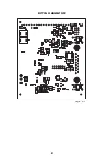
Страница 52: ...49 BOTTOM COMPONENT SIDE Aug 09 2007...
Страница 53: ...APPENDIX V DIMENSIONAL DRAWINGS XFM WITHOUT READOUT 50...
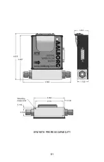
Страница 54: ...XFM WITH PROFIBUS CAPABILITY 51...
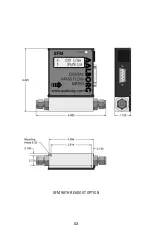
Страница 55: ...XFM WITH READOUT OPTION 52...


