background image

40

APPENDIX I

AALBORG

7

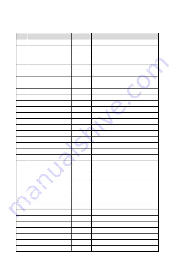
XFM  EEPROM Variables Rev.A0 [12/19/2006] 

Gas Independent Variables

INDEX

NAME

DATA TYPE

NOTES

0

BlankEEPROM

char[10]

Do not modify.  Table  Revision [PROTECTED]

1

SerialNumber

char[20]

Serial Number [PROTECTED]

2

ModelNumber

char[20]

Model Number [PROTECTED]

3

SoftwareVer

char[10]

Firmware Version [PROTECTED]

4

TimeSinceCalHr

float

Time since last calibration in hours.

5

Options1

uint

Misc. Options*

6

BackLight

int

Back Light Level [0-4095]

7

AddressRS485

char[4]

Two character address for RS485 only

8

GasNumber

int

Current Gas Table Number [0-9]

9

FlowUnits

int

Current Units of Measure [0-22]

10

AlarmMode

char

Alarm Mode ['E’- Enabled, 'D’ - Disabled]

11

LowAlarmPFS

float

Low Flow Alarm Setting [%FS] 0-Disabled

12

HiAlarmPFS

float

High Flow Alarm Setting [%FS] 0-Disabled

13

AlmDelay

uint

Flow Alarm Action Delay [0-3600sec] 0-Disabled

14

RelaySetting

char[4]

Relays Assignment Setting (N, T, H, L, R, M)

15

TotalMode

char

Totalizer Mode ['E’- Enabled, 'D’ - Disabled]

16

Total

float

Totalizer Volume in %*s (updated every 6 min)

17

TotalFlowStart

float

Start Totalizer at flow [%FS] 0 - Disabled

18

TotalVolStop

float

Totalizer Action Limit Volume [%*s] 0-Disabled

19

KfactorMode

char

D-Disabled, I-Internal, U-User Defined

20

KfactorIndex

int

Internal K-Factor Index [0-35]**

21

UserDefKfactor

float

User Defined K-Factor

22

UDUnitKfactor

float

K-Factor for User Defined Units of Measure

23

UDUnitTimeBase

int

User Defined Unit Time Base [1, 60, 3600 sec]

24

UDUnitDensity

char

User Defined Unit Density Flag [Y, N]

25

AoutScaleV

float

DAC 0-5 Vdc Analog Output Scale

26

AoutOffsetV

float

DAC 0-5 Vdc Analog Output Offset

27

AoutScale_mA

float

DAC 4-20mA Analog Output Scale 

28

AoutOffset_mA

float

DAC 4-20mA Analog Output Offset 

29

SensorZero

uint

DPW value for Sensor Zero [0-1023]

30

Klag [0]

float

DRC Lag Constant [Do Not Alter]

31

Klag [1]

float

DRC Lag Constant [Do Not Alter]

32

Klag [2]

float

DRC Lag Constant [Do Not Alter]

33

Klag [3]

float

DRC Lag Constant [Do Not Alter]

34

Klag [4]

float

DRC Lag Constant [Do Not Alter]

Содержание XFM 17

Страница 1: ...Technical Data Sheet No TD0701M Rev D Date of Issue November 2016 OPERATING MANUAL XFM DIGITAL MASS FLOW METERS...

Страница 2: ...5 OPERATING INSTRUCTIONS 5 1 Preparation and Warm Up 5 2 Swamping Condition 5 3 XFM Parameters Settings 5 3 1 Engineering Units Settings 5 3 2 Gas Table Settings 5 3 3 Totalizer Settings 5 3 4 Flow Al...

Страница 3: ...t calibration 8 RS 485 RS 232 SOFTWARE INTERFACE COMMANDS 8 1 General 8 2 Commands Structure 8 3 ASCII Commands Set 9 TROUBLESHOOTING 9 1 Common Conditions 9 2 Troubleshooting Guide 9 3 Technical Assi...

Страница 4: ...Aalborg7 if you purchased your Mass Flow Meter directly and request a Return Authorization Number RAN Equipment returned without an RAN will not be accepted Aalborg7 reserves the right to charge a fee...

Страница 5: ...s of the piping system including fer rules and fittings for dust or other contaminant s When connecting the gas system to be monitored be sure to observe the direc tion of gas flow as indicated by the...

Страница 6: ...do so might cause damage to this device Be sure to check if the wiring and the polarity of the power supply is correct before turning the power ON Wiring error may cause damage or faulty operation XFM...

Страница 7: ...converter adapter must be configured for multidrop 2 wire half duplex mode The transmitter circuit must be enabled by TD or RTS depending on which is available on the converter adapter Settings for t...

Страница 8: ...t Disconnect the power to the unit remove the faulty condition and reconnect the power The fuse will reset once the faulty con dition has been removed DC Power cable length may not exceed 9 5 feet 3 m...

Страница 9: ...tronic control circuit The measured temperature gradient at the sensor windings is linearly proportional to the instantaneous rate of flow taking place An output signal is generated that is a function...

Страница 10: ...E DROP 0 18 PSID at 10 L min flow 8 psi at 100 L min flow See Table IV for pressure drops associated with various models and flow rates GAS AND AMBIENT TEMPERATURE 32 F F to 122 F F 0 F C to 50 F C 14...

Страница 11: ...mpression fittings Model XFM 47 57 standard 3 8 compression fittings Model XFM 67 standard 1 2 compression fittings Model XFM 77 standard 3 4 FNPT fittings Optional 1 8 or 3 8 compression fittings and...

Страница 12: ...2 00 0 to 5 07 0 to 1 01 0 to 10 08 0 to 2 02 0 to 20 09 0 to 5 03 0 to 50 10 0 to 10 04 0 to 100 05 0 to 200 06 0 to 500 TABLE I XFM 17 LOW FLOW MASS FLOW METER TABLE II XFM 37 MEDIUM FLOW MASS FLOW...

Страница 13: ...BD 30 TBD TBD TBD 40 TBD TBD TBD 50 TBD TBD TBD XFM 47 60 TBD TBD TBD 100 TBD TBD TBD XFM 57 200 TBD TBD TBD XFM 67 500 TBD TBD TBD XFM 77 1000 TBD TBD TBD MODEL WEIGHT SHIPPING WEIGHT XFM 17 transmit...

Страница 14: ...the next two seconds the RS 485 network address the analog output set tings and currently selected gas calibration table will be displayed applicable for LCD option only Figure b 3 XFM second Banner...

Страница 15: ...f more than 10 above the maximum flow rate of the Mass Flow Meter is taking place a condition known as swamping may occur Readings of a swamped meter cannot be assumed to be either accurate or linear...

Страница 16: ...ec mL Milliliter per second 3 2 mL min mL Milliliter per minute 4 3 mL hr mL Milliliter per hour 5 4 L sec Ltr Liter per second 6 5 L min Ltr Liter per minute 7 6 L hr Ltr Liter per hour 8 7 m3 sec m3...

Страница 17: ...n conditions become true when the totalizer reading and preset Stop at Total volumes are equal 14 Note Once Flow Unit of Measure is changed the Totalizer s Volume Mass based Unit of Measure will be ch...

Страница 18: ...D connector see Figure c 1 XFM configuration jumpers 5 3 4 Flow Alarm Settings XFM provides the user with a flexible alarm warning system that monitors the Gas Flow for conditions that fall outside c...

Страница 19: ...rm H High Flow Alarm condition Low Flow Alarm L Low Flow Alarm condition Range between H L R Range between High and Low Flow Alarm condition Manual Enabled M Activated regardless of the Alarm and Tota...

Страница 20: ...sure that no seep age or leak occurs into the meter it is good practice to temporarily disconnect the gas source The Auto Zero may be initiated via digital communication interface or locally by pressi...

Страница 21: ...s considered successful The status LED will return to a constant GREEN light and the screen below will appear Figure b 7 XFM during the Auto Zero procedure If the device was unable to adjust the Senso...

Страница 22: ...ERROR reset or maintenance service is required for return in to the normal operation Constant RED 1 3 CPU Temperature too high Electronics Overheating Flashing RED AMBER 2 4 Sensor in the warm up sta...

Страница 23: ...ilter is built into the inlet of the flow transducer The filter screen and the flow paths may require occasional cleaning as described below There is no other recommended maintenance required It is go...

Страница 24: ...nt RFE is connected to the inlet fitting Carefully disassemble the RFE from the inlet connection The 50 micron filter screen will now become visible Push the screen out through the inlet fitting Clean...

Страница 25: ...e the block and connected screens Clean each of the removed parts as necessary If alcohol is used for cleaning allow time for drying Inspect the flow path inside the transducer for any visible signs o...

Страница 26: ...ulti meter for analog output calibration only an insulated plastic screwdriver a flow regulator for example metering needle valve installed upstream from the Mass Flow Meter and a pressure regulated s...

Страница 27: ...dexes 113 115 117 118 119 121 123 125 127 129 131 133 Actual flow values are entered in normalized fraction format 100 000 F S cor responds to 1 000000 flow value and 0 000 F S corresponds to 0 000000...

Страница 28: ...a new value check the XFM flow rate against the cal ibrator and if required perform additional adjustments for Index 133 If a simple communication terminal is used for communication with the XFM then...

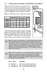
Страница 29: ...Output Scale 28 AoutOffset_mA DAC 4 20mA Analog Output Offset Note The analog output available on the XFM Digital Mass Flow Meter was calibrated at the factory for the specified gas and full scale flo...

Страница 30: ...Update D 7 3 2 Gas flow 0 5 Vdc analog output calibration 1 Install jumpers J7A J7B and J7C on the PC board for 0 5 Vdc output see Table VI 2 Connect a certified high sensitivity multi meter set for t...

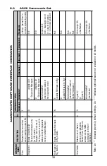
Страница 31: ...printable ASCII characters For RS 485 interface the start character is always The command string is terminated with a carriage return line feeds are automatically stripped out by the XFM See section...

Страница 32: ...evice with unknown address 1 Make sure only one device which address must be changed is connected to the RS 485 network 2 Type the memory write command with global address 00 MW 7 XX CR where XX the n...

Страница 33: ...D E D disable LCD Diagnostic Messages D D NO ARGUMENT read current status of the diagnostic word D 0x0 L 9 E 0x0 diagnostic word 9 current LED status E LCD mode enabled Roll back to N 2 feature Enable...

Страница 34: ...Display zero value ZV zero value Flow Alarms Sets reads the status of the gas flow alarms Note High and Low limits have to be entered in the F S High alarm value has to be more than Low alarm value Al...

Страница 35: ...1 2 relay 2 N R1N or R2N T R1T or R2T H R1H or R2H L R1L or R2L R R1R or R2R M R1M or R2M S RxN RxT RxH RxL RxR RxM Totalizer Sets and controls action of the flow totalizer NOTE If Warm Up Delay opti...

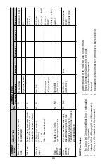
Страница 36: ...h F S engineering unit See list of the internal K factors in the operating manual 9 K D disable sets K 1 KD I Internal K factor No argument enable previously set internal K factor KI value Gas Gas Ind...

Страница 37: ...hr U mL hr L sec U L sec L min U L min L hr U L hr m3 sec U m3 sec m3 min U m3 min m3 hr U m3 hr f3 sec U f3 sec f3 min U f3 min f3 hr U f3 hr g sec U g sec g min U g min g hr U g hr kg sec U kg sec...

Страница 38: ...me unit was calibrated 11 C R read timer Value in Hours C set timer to zero CC Full Scale Returns the full scale rated flow in L min Note This term is not multiplied by the current K factor 12 E Value...

Страница 39: ...t the instrument is not functioning properly please check for the following common conditions first Are all cables connected correctly Are there any leaks in the installation Is the power supply corre...

Страница 40: ...rned out or damaged Return XFM to factory for repair Analog flow output scale and offset variable are corrupted Restore original EEPROM scale and offset variable or perform analog output recalibration...

Страница 41: ...s connected in the installation with back pressure conditions and gas leak exist in the system Locate and correct gas leak in the system If XFM has internal leak return it to factory for repair 11 The...

Страница 42: ...rence gas 10 CALIBRATION CONVERSIONS FROM REFERENCE GASES The calibration conversion incorporates the K factor The K factor is derived from gas density and coefficient of specific heat For diatomic ga...

Страница 43: ...L R M 15 TotalMode char Totalizer Mode E Enabled D Disabled 16 Total float Totalizer Volume in s updated every 6 min 17 TotalFlowStart float Start Totalizer at flow FS 0 Disabled 18 TotalVolStop float...

Страница 44: ...ot Alter 41 Kgain 5 float Gain for DRC Lag Constant Do Not Alter 42 Zero_T float Resistance when last AutoZero was done 0 4095 count 43 Tcor_K float Resistance correction coefficient PFS count 44 Alar...

Страница 45: ...m sensor counts 116 SensorTbl 1 Flow float Actual Flow in PFS 0 1 117 SensorTbl 2 Sensor Value uint 20 0 F S A D value from sensor counts 118 SensorTbl 2 Flow float Actual Flow in PFS 0 2 119 SensorTb...

Страница 46: ...0 3224 0 3514 2 413 14 Butane C4H10 2631 4007 2 593 15 1 Butane C4H8 0 2994 0 3648 2 503 16 2 Butane C4H8 CIS 0 324 0 336 2 503 17 2 Butane C4H8 TRANS 0 291 0 374 2 503 18 Carbon Dioxide CO2 7382 201...

Страница 47: ...romethane Freon 13 B1 CBrF3 3697 1113 6 644 1 3 Butadiene C4H6 3224 3514 2 413 Butane C4H10 2631 4007 2 593 1 Butene C4H8 2994 3648 2 503 2 Butene C4H8 CIS 324 336 2 503 2 Butene C4H8 TRANS 291 374 2...

Страница 48: ...oride C2H5Cl 3891 244 2 879 Ethylene C2H4 60 365 1 251 Ethylene Oxide C2H4O 5191 268 1 965 Fluorine F2 9784 1873 1 695 Fluoroform Freon 23 CHF3 4967 176 3 127 Freon 11 CCl3F 3287 1357 6 129 Freon 12 C...

Страница 49: ...oride CH3Cl 6299 1926 2 253 Methyl Fluoride CH3F 68 3221 1 518 Methyl Mercaptan CH3SH 5180 2459 2 146 Methyl Trichlorosilane CH3 SiCl3 2499 164 6 669 Molybdenum Hexafluoride MoF6 2126 1373 9 366 Monoe...

Страница 50: ...35 1592 6 516 Sulfuryl Fluoride SO2F2 3883 1543 4 562 Tetrafluoroethane Forane 134A CF3CH2F 5096 127 4 224 Tetrafluorohydrazine N2F4 3237 182 4 64 Trichlorofluoromethane Freon 11 CCl3F 3287 1357 6 129...

Страница 51: ...48 APPENDIX IV COMPONENT DIAGRAM TOP COMPONENT SIDE Aug 09 2007...

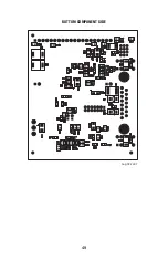
Страница 52: ...49 BOTTOM COMPONENT SIDE Aug 09 2007...

Страница 53: ...APPENDIX V DIMENSIONAL DRAWINGS XFM WITHOUT READOUT 50...

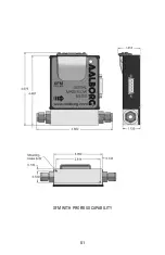
Страница 54: ...XFM WITH PROFIBUS CAPABILITY 51...

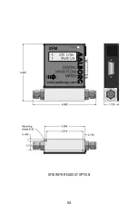
Страница 55: ...XFM WITH READOUT OPTION 52...

Страница 56: ...e permitted to control and operate the equipment covered by this warranty Anything to the contrary will automatically void the liability of Aalborg7 and the provisions of this warranty Defective produ...

Отзывы: