TRACKING switches.
B. Because both voltage and current of the SLAVE supply track the MASTER supply,
the maximum current and voltage are set using the MASTER controls. Using the MASTER
supply output jacks, follow the instructions for "Setting Current Limit" (4-2 Section).
Remember that the actual current output at the MATER supply output jack is double the
reading on the SLAVE indicator meter. Then push the output on/off key to enter voltage and
current setting.
C. Adjust the output voltage to the desired level using the MASTER VOLTAGE controls.
D. Turn off the power supply and the equipment to be powered during hook-up.
E. Connect the positive polarity of the device being powered to the red (+) terminal of the
MASTER power supply.
F. Connect the negative polarity of the device being powered to the black (-) terminal of
the MASTER power supply.
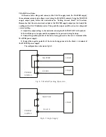
The configuration as shown in Fig.4-5.
_
POWER
SUPPLY
M AST ER
S LAVE
+
+
_
Fig .4-5 Paral lel Tracki ng Op eratio n.
L OAD
L OAD
_
POWER
SUPPLY
MAST ER
SL AV E
+
+
_
L OAD
Fig .4-3 Sin gle Supp ly
Содержание Precision AC- DC Power Supply
Страница 12: ...Fig 3 2 Rear Panel...


