background image

                    In  this  mode,  maximum  voltage  of both supplies is set using the MASTER VOLTAGE 

controls (voltage at output terminals of the SLAVE supply tracks the voltage at the output 

terminals of the MASTER supply). Also, in this mode of operation the positive terminal (red) of 

the SLAVE supply is connected to the negative terminal (black) of the MASTER supply. 


This allows the two supplies to be used as one 0 to double rating voltage supply. 

c. When both switches are engaged (in), the unit is in the TRACKING PARALLEL mode. In this 

mode the MASTER and SLAVE supplies are wired together in parallel and both the maximum 

current and voltage are set using the MASTER controls. 

The    MASTER and SLAVE outputs can be used as two individual (but tracking) power supplies or 

just the MASTER output can be used as a 0 to rating voltage supply with a 0 to double rating 

current capability. 

16    "    +    ": output terminal: positive polarity output terminal for the MASTER supply. 

19    "    +    ": output terminal: positive polarity output terminal for the SLAVE    supply. 

17    "    GND    " terminal: Earth and chassis ground. 

20    "    GND    " terminal: Earth and chassis ground. 

18  "  -  ": output terminal: Negative polarity output terminal for the MASTER supply. 

21  "  -  ": output terminal: Negative polarity output terminal for the SLAVE supply. 

23    "    +    ": output terminal: positive polarity output terminal for 5V supply. 

24  "  -  ": output terminal: Negative polarity output terminal for 5V supply. 

29 Output ON/OFF switch: DC power supply output when switch is engaged (in).And when output is 

off, both the voltage and current can be adjusted before the output is resumed. 

28 Output indicator: lights when switch is engaged (in). 

3-2 Rear Panel 

25  Fuse holder 

26  Power cord 

27  Fan 

30    AC voltage select switch 

4. OPERATION INSTRUCTIONS 

4-1 Precaution 

(1). AC input 

AC input should be within the range of line voltage±10% 50/60Hz. 

(2). Installation 

Avoid using the supply in a place where the ambient temperature exceeds 40 C. The heat sink 

located at the rear of the supply must have sufficient air space for radiation. 

Содержание Precision AC- DC Power Supply

Страница 1: ...Dual Channel 0 30V 5A max or 0 60V single channel AA Portable Power Corp http www batteryspace com Address 860 S 19th St Unit A Richmond CA 94804 Tel 510 525 2328 Fax 510 439 2808 Email Sales battery...

Страница 2: ...output range The front panel current controls can be used to establish the output current limit overload or shout circuit when the supply is used as a constant voltage source independent or tracking m...

Страница 3: ...utput on off key to enter voltage and current setting C Adjust the output voltage to the desired level using the MASTER VOLTAGE controls D Turn off the power supply and the equipment to be powered dur...

Страница 4: ...h its Kindred has not This function is that when the output has been cut off the both intending voltage and current can be preset though in model A B condition only the intending voltage can be adjust...

Страница 5: ...peration 1 Output current range 0 rating voltage continuously adjustable 2 Regulation Line regulation 0 01 3mV Load regulation 0 01 3mV rating current 3A Load regulation 0 02 5mV rating current 3A 3 R...

Страница 6: ...for Setting Current Limit INDEPENDENT USE OF MASTER OR SLAVE SUPPLY section of this manual using the MASTER CURRENT control NOTE Because the supplies are being used in series either CURRENT control c...

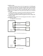
Страница 7: ...R SUPPLY LOAD MASTER SLAVE LOAD _ _ Fig 4 2 Indep endent Operatio n Slave tracking error 0 5 10mV of the master No load with load add Load regulation 300mV B Single supply Fig 4 3 2 6 Meter A Display...

Страница 8: ...ORS V 1 C V LABORATORY DC POWER SUPPLY CURRENT POWER 22 13 ON 29 8 7 28 OUTPUT ON O FF GND OFF 12 21 19 20 C V C C PAR SLAVE VOLTAGE GND 17 18 15 14 16 INDEP SERIES PARALLEL TRACKING C C MASTER 3 4 A...

Страница 9: ...ator to light 4 Adjust the CURRENT control for the desired current limit Read the current value on the A meter 5 The current limit overload protection has now been preset Do not change the CURRENT con...

Страница 10: ...justment of the output voltage of the MASTER supply Also functions as adjustment control for the maximum output voltage of the SLAVE supply when either parallel or series tracking operation Voltage co...

Страница 11: ...rity output terminal for the MASTER supply 19 output terminal positive polarity output terminal for the SLAVE supply 17 GND terminal Earth and chassis ground 20 GND terminal Earth and chassis ground 1...

Страница 12: ...Fig 3 2 Rear Panel...

Отзывы: