A.O. Smith DB/DW-720-1810 Скачать руководство пользователя страница 17

17

BYPASS BALANCING

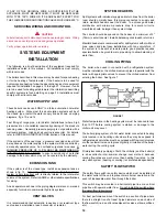
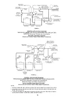
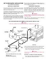
With systems where water temperature can be expected to drop
appreciably due to long standby periods, or heavy draw down, a
bypass pipe of at least 1" size with a balancing cock should be
installed between the boiler inlet and outlet (see fig. 10).  When
the system first starts, the valve should be slowly opened until the
condensing ceases.  This adjustment remains at a permanent
setting to establish required temperature rise across the boiler.

LINEAR-TEMP SPACE HEATING APPLICATIONS

Controlling of these systems is decided mainly by the type of
building system controlling that is desired.  A single boiler
installation might be controlled directly from space temperature
thermostat(s).  Multiple boiler installations are more effective when
the boilers are sequenced in and out of operation by some form of
main water temperature controller.  With one or two boilers,
individual control set at progressive temperature may be used.
For more than two boilers, electronic sequencing controlling is
recommended.

Individual controls, or the separate stages of a step controller,
should fire a boiler and also start the boiler loop circulator whenever
that boiler is fired.  Some large installations may require the firing
of more than one boiler per stage.

The system or primary circulator may or may not be controlled by
the boiler sequencer.  When this pump is operated through the
first switch of any type of step controller, care should be taken to
determine if a motor starter is needed due to insufficient switch
capacity.

If the primary pump is controlled by a manual switch or any other
controllers, the electric current supply to the boiler group should
be through the primary pump controller.  The fast response of
A.O. Smith boilers eliminates any need to maintain boiler
temperature when the system is satisfied.  Wiring should always
prevent firing of boiler(s) when there is no water flow in the mains.

Installation diagrams show safety flow switches in the outlet piping
from each boiler as good protection against any boiler being fired
when the boiler loop circulator is not in operation.

These safety flow switches will also provide some protection if
there is a loss of water.

LINEAR-TEMP multiple boiler installations are especially adapted
to the use of outdoor reset for main water temperatures.  This
feature is not mandatory but offers smooth, efficient operation of
a modern system.

Outdoor reset systems should utilize an automatic shutdown
control if there is a continuous recirculating main and/or if the
entire building is not under control of space temperature
thermostats.  A single bulb outdoor sensing control will serve this
requirement.  This precaution will prevent overheating of halls,
stairways or other uncontrolled areas.  There are occasions when
outdoor temperatures are temporarily too warm for even a
moderate amount of heating in these areas.

Space temperature controlling can be varied to meet the building
requirements.  Either the single thermostat, as shown, or multiple
zone thermostats should control a common relay.  This relay
controls electric power to the system primary circulator and to the
main water temperature controller.  This provides for water
movement in the system before the main temperature controller
can start the secondary circulating pump or fire the boiler.

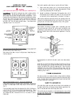
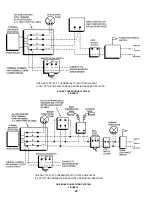
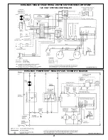
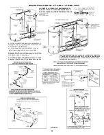
Figure 11 shows a typical field wiring diagram  for a single stage
boiler  LINEAR-TEMP installation.  The boiler may be controlled
by a main temperature controller as shown or may include outdoor
reset if desired.

The following fig’s. 11 thru 13 are shown as layouts for various
choices of controls often found in commercial heating.  These
layouts are not intended to be wiring diagrams and only show the
relation of one device to another in the system.

Figure 11 is a typical layout of controls for two boilers with two
circulators and thermal balancers plus optional outdoor reset
control.

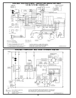
Figure 12 is shown as a typical control group for various multiple
boiler installations, and is not intended to imply that this is the
only arrangement to be considered.  Commercial size installations
are always best when designed to individual building requirements.
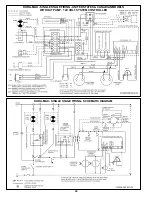
FIGURE 13

LINEAR-TEMP SPACE HEATING INSTALLATIONS

A. New Installation

The A.O. Smith LINEAR-TEMP system has been designed to
provide efficient, trouble-free operation of these boilers with any
of the following conditions:

unknown system flow rate.

varying flow rates as with zoned systems and 3-way valve
system.

multiple boiler installations.

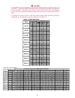
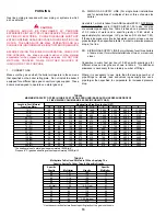
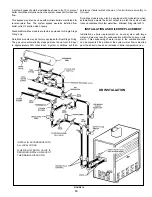
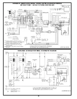
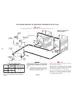
Figure 14 shows piping and accessory arrangement for 1 or more
boilers pumped independently of the primary system mains.  Pipe
sizing and boiler loop pump selection data, are shown in table 4 for
several different temperature rises across various boiler sizes.

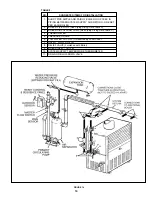
Total heating requirements for the building can be supplied by a
series of boiler loops all connecting to a common pipe joining the
system supply and return mains.  The supply and return branches
of each boiler loop must join the common pipe only a short nipple
length apart.  The different sets of branches should be installed
reasonably close together, but not necessarily to the short nipple
length as required for the supply and return of each set.  These
branches may be made with tees or with welded connections.

The installer is reminded that the total boiler flow rates do not
have to match the system flow rate.  Flow rates through heat

Содержание DB/DW-720-1810

Страница 1: ...the fire department Installation and service must be performed by a qualified installer service agency or the gas supplier PRINTED IN U S A 2221 0302 CAUTION TEXT PRINTED OR OUTLINED IN RED CONTAINS I...

Страница 2: ...ars on the product Refer to the parts lists for more information For Technical Assistance call A O Smith Technical Information Center at 1 800 527 1953 WARNING THE INLET OUTLET WATER MANIFOLD ON YOUR...

Страница 3: ...inches mm inches mm inches mm inches mm inches mm A 46 1 2 1181 52 1 5 1326 57 3 4 1467 52 7 8 1343 58 1 2 1486 64 1 2 1638 69 1 2 1765 75 1905 82 1 2 2096 B 29 5 8 752 29 5 8 752 29 5 8 752 32 3 4 8...

Страница 4: ...03 1 336 1 203 1 114 1 093 1 002 954 925 859 354 LPH 22 762 15 175 12 646 11 381 9 105 8 430 7 587 6 504 6 323 5 691 5 058 4 552 4 215 4 139 3 794 3 613 3 502 3 252 1 350 000 GPH 6 709 4 473 3 727 3 3...

Страница 5: ...d every water storage tank in a hot water supply system The storage tank temperature and pressure relief valve must comply with the applicable construction provisions of the Standard for Relief Valves...

Страница 6: ...temperature rise at LO thermostat sensor location will continue to rise until shut off by high limit or drop causing heater to go back to full input Other system design temperatures will require rese...

Страница 7: ...utoff device must be installed in the boiler outlet at the time of installation For installation locations with elevations above 2 000 feet 610 M refer to the HIGH ALTITUDE INSTALLATIONS section of th...

Страница 8: ...sion must be made if the boiler is installed in confined space or a small boiler room to accommodate draft hood spillage and avoid risks described above The upper air opening called for in the AIR REQ...

Страница 9: ...s outlined above return doors windows exhaust fans fireplace dampers and any other gas burning appliance to their previous conditions of use GAS CONNECTIONS WARNING THIS BOILER IS NOT INTENDED TO OPER...

Страница 10: ...of 0 3 inches of water and a specific gravity of 0 60 which is approximately for natural gas LP gas has an S G of about 1 53 If the service pressure is five inches water column or less use one pipe si...

Страница 11: ...u per Cubic Foot of Gas 1 000 With a cubic foot per hour demand of 3 360 and with 50 lineal feet of gas supply line table 4 shows a pipe size of 3 is required NOTE For other than 60 specific gravity a...

Страница 12: ...agrams is recom mended especially for modern commercial hydronic systems VENT VALVES It is recommended that automatic loose key or screwdriver type vent valves be installed at each convector or radiat...

Страница 13: ...ockwise 3 For lower flow rate turn the range adjusting screw counterclockwise Where units are installed in multiples each boiler must be individually protected by a safety flow switch CIRCULATING PUMP...

Страница 14: ...st temperature which satisfies the user s hot water needs This will also provide the most energy efficient operation of the water heater and minimize scale formation SETTING THE WATER TEMPERATURE AT 1...

Страница 15: ...determine if boiler will shut down or if unit will return smoothly to full input Dura Max models may also be equipped with modulation which automatically adjusts the boiler output to match the system...

Страница 16: ...TRIC POWER TO BUILDING CIRCULATOR 2 MAIN FLOW SWITCH PROVES MAIN WATER FLOW BEFORE ENERGIZING SEQUENCING AND RESETTING CONTROLS 3 OUTDOOR THERMOSTAT REQUIRED IF BUILDING CONTROLS DO NOT PROVIDE AUTOMA...

Страница 17: ...gle bulb outdoor sensing control will serve this requirement This precaution will prevent overheating of halls stairways or other uncontrolled areas There are occasions when outdoor temperatures are t...

Страница 18: ...ence the boiler on and off in relation to the load on the system Pressure drop includes the loss through 40 12 m of pipe and normal fittings Water Category Grain Hardness per Gal Soft 1 through 7 5 No...

Страница 19: ...EACH BOILER 2 BOILER PIPE LOOP See Piping Sizing Data Table 3 3 BOILER CIRCULATING PUMP See Piping Sizing Data Table 3 4 THERMOMETER 5 PRESSURE GAUGE 6 LOW WATER CUT OFF If Required By Local Code 7 SA...

Страница 20: ...LENT IF ANY OF THE ORIGINAL WIRES AS SUPPLIED MUST BE REPLACED USE ONY TYPE 105 C THERMOPLASTIC OR ITS EQUIVALENT IF ANY OF THE ORIGINAL WIRES AS SUPPLIED MUST BE REPLACED BOILER CONVENTIONAL SYSTEM F...

Страница 21: ...21 DURA MAX PUMP MOUNT SINGLE STAGE SCHEMATIC DIAGRAM DURA MAX SINGLE STAGE FIRING UNITED STATES MODELS WITH PUMP 120 VOLT SYSTEM CONTROLLER...

Страница 22: ...22 DURA MAX PUMP MOUNT DUAL STAGE SCHEMATIC DIAGRAM DURA MAX DUAL STAGE FIRING UNITED STATES MODELS WITH PUMP 120 VOLT SYSTEM CONTROLLER...

Страница 23: ...23 DURA MAX PUMP MOUNTED MODULATING SCHEMATIC DIAGRAM DURA MAX MODULATED FIRING UNITED STATES MODELS WITH PUMP 120 VOLT SYSTEM CONTROLLER...

Страница 24: ...24 DURA MAX SINGLE STAGE FIRING SCHEMATIC DIAGRAM DURA MAX SINGLE STAGE FIRING UNITED STATES CANADIAN MODELS WITHOUT PUMP 120 VOLT SYSTEM CONTROLLER...

Страница 25: ...25 DURA MAX DUAL STAGE FIRING SCHEMATIC DIAGRAM DURA MAX DUAL STAGE FIRING UNITED STATES CANADIAN MODELS WITHOUT PUMP 120 VOLT SYSTEM CONTROLLER...

Страница 26: ...26 DURA MAX MODULATED FIRING SCHEMATIC DIAGRAM DURA MAX MODULATED FIRING UNITED STATES CANADIAN MODELS WITHOUT PUMP 120 VOLT SYSTEM CONTROLLER...

Страница 27: ...or the threshold type of water treatment is recommended This will protect the dishwashers coffee urns water heaters water piping and other equipment When water softening or water treatment is not prac...

Страница 28: ...ERRUPTION OR CIRCULATOR FAILURE CAUTION PUMP MUST BE RATED FOR SYSTEM OPERATING TEMPERA TURES AND PRESSURE SEE TABLE 7 FOR GUIDE TO PIPE AND PUMP SIZING SAFETY RELIEF VALVE RATING SHOULD NOT EXCEED PR...

Страница 29: ...CING BOILER HOWEVER LOCAL CODES SHALL GOVERN THEIR USAGE ALL PIPING MUST BE SUPPORTED IMPORTANT THE INSTALLATION OF SAFETY FLOW SWITCHES AS SHOWN IS REQUIRED TO PROTECT THE BOILER IN CASE OF WATER SER...

Страница 30: ...BE RATED FOR SYSTEM OPERATING TEMPERATURE AND PRESSURE SAFETY RELIEF VALVE RATING SHOULD NOT EXCEED PRESSURE CAPACITY OF ANY COMPONENT IN THE SYSTEM INSTALL IN ACCORDANCE WITH ALL LOCAL CODES BALL VA...

Страница 31: ...T EXCEED PRESSURE CAPACITY OF ANY COMPONENT IN THE SYSTEM PIPE RELIEF VALVES TO OPEN DRAIN NOTE METRIC SIZING IS FOR COMPARISON ONLY ALL UNITS CONSTRUCTED WITH TANK FITTING MEASURED IN INCHES TANK TEM...

Страница 32: ...ler to maximum setting causing a call for heat and allowing unit to run until High Limit trips 3 Reset Manual High Temperature Safety Limit Control to original temperature setting 4 Push the reset but...

Страница 33: ...ERVICE TECHNICIAN TO INSPECT THE APPLIANCE AND TO REPLACE ANY PART OF THE CONTROL SYSTEM AND ANY GAS CONTROL WHICH HAS BEEN UNDER WATER 1 MAKE SURE BOILER AND SYSTEM ARE FILLED WITH WATER AND ALL AIR...

Страница 34: ...NS section 1 Attach a pressure gauge or a manometer to the gauge port Check for correct manifold pressure PRESSURE SHOULD NOT EXCEED VALUE INDICATED ON RATING PLATE 2 Use this formula to clock the met...

Страница 35: ...te label Voltage 24 vac is supplied by transformer Appliance is wired according to wiring diagram NOTE Cross wiring the 24 volt circuit of the relay will short the transformer All wire terminals conne...

Страница 36: ...wer supply NO Is ignition cable firmly plugged into pilot assembly Securely connect cable and module and or ground wire Is ground wire firmly attached to pilot assembly and GND terminal on module YES...

Страница 37: ...nto pilot assembly and module Securely connect cable Is ground wire firmly attached to pilot assembly and GND and or ground wire terminal on module YES Replace cable and or NO Are ignition cable and g...

Страница 38: ...curely attached to the main firmly valve operator on the gas control and to terminals MV and MV PV on ignition module YES YES Replace main gas valve Ensure the ground wire and igntion cable are separa...

Страница 39: ...ior of the inlet outlet manifold through the pressure relief valve tapping GENERAL MAINTENANCE These boilers are designed to give many years of efficient and satisfactory service when properly operate...

Страница 40: ...pect to ensure tubes are free of scale and deposits If scaled remove deposits with a stiff wire brush or mechanical tube cleaner to bare metal Install new O rings and install return bends Flush system...

Страница 41: ...claimed defective part to such distributor c All cost necessary or incidental for any material and or permits required for installation of the replacement 4 LIMITATIONS ON IMPLIED WARRANTIES Implied...

Страница 42: ...42...

Страница 43: ...43...

Страница 44: ...44 REPLACEMENT PARTS 5621 W 115TH STREET ALSIP IL 60803 PHONE 800 433 2545 FAX 800 433 2515 www hotwater com E Mail parts hotwater com...

Отзывы: