52
52
52
52
52
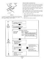
NORMAL OPERATING SEQUENCE WITH INTERMITTENT
IGNITION CONTROLS (I.I.D.)
1.
System control calls for boiler operation.
2.
Spark begins at pilot burner.
3.
Pilot gas control valve is energized. Gas flows to pilot burner.
4.
Pilot burner gas ignites. The sensing probe on the pilot burner
senses the presence of the pilot flame. The spark stops after
a few seconds.
NOTE:
If the pilot gas isn’t present or doesn’t ignite after
15 seconds, the spark and pilot gas will stop, wait 5
minutes, and retry or unit must be manually reset..
5.
Main gas control valve is energized and main burner gas
ignites.
NOTE:
If gas interruption occurs during boiler operation, the
sensing probe will detect flame failure and within
.8 seconds de-energize the main and pilot burner gas
control valves. The operation of the control will revert
back to step 2 in the foregoing.
6.
System control stops boiler operation. Main and pilot burners
are extinguished.
HIGH ALTITUDE INSTALLATIONS
IN CANADA
Acceptance of these models for use at altitudes above 2000 feet
(600 m) is based on field test of the individual installation by the
provincial/state authority having jurisdiction.
IN THE U.S.A.
WARNING
INSTALLATIONS ABOVE 2000 FEET REQUIRE REPLACEMENT
OF THE BURNER ORIFICES IN ACCORDANCE WITH SECTION
8.1.2 OF THE NATIONAL FUEL GAS CODE (ANSI Z223.1). FAILURE
TO REPLACE THE ORIFICES WILL RESULT IN IMPROPER AND
INEFFICIENT OPERATION OF THE APPLIANCE RESULTING IN
THE PRODUCTION OF INCREASED LEVELS OF CARBON
MONOXIDE GAS IN EXCESS OF SAFE LIMITS WHICH COULD
RESULT IN SERIOUS PERSONAL INJURY OR DEATH.
For specific orifice requirements, please refer to the appropriate
section of the National Fuel Gas Code ANSI Z223.1 or
CGA 2.17-M91.
You should contact your gas supplier for any specific changes
which may be required in your area.
Ratings specified by manufacturers for most boilers apply for
elevations up to 2000 feet (600 m). For elevations above 2000 feet
(600 m) ratings must be reduced by a rate of 4% for each 1000 feet
(300 m) above sea level.
Example: If a boiler is rated at 610,000 Btu/hr. at sea level, to operate
the boiler at 5000 feet (1500 m) it must be derated by 20% (4% x 5)
to a new rating of 488,000 Btu/hr.
A. O. Smith does build some models specifically for high altitude
service. Please check the rating plate before making changes.
The input reduction is primarily achieved by reducing the size of
the main burner orifices. To do this, the main burner orifices require
replacement with orifices sized for the particular installation
elevation. When ordering, be sure to state the model number and
the altitude of the location where the boiler is being installed.
Upon field deration of the boiler, adjustment to the gas pressure
regulator is required. See CHECKING AND ADJUSTING THE
INPUT in this manual for inlet and manifold pressure requirements.
Also, due to the input rating reduction required at high altitudes,
the output rating of the appliance is also reduced and should be
compensated for in the sizing of the equipment for applications.
THERMAL BALANCER
Figure 47 shows the internal wiring of the thermal balancer. The
device may be tested after disconnecting the four leads from their
respective terminals on the unit.
1.
Apply a test light to the yellow and red leads.
•
The lamp should light as the contact in this circuit is
normally closed when the resistor is cool.
2.
Apply a light to the black and yellow leads.
•
The lamp should not light as the contact in this circuit is
normally open when the resistor is cool.
3.
Remove the test light.
4.
Apply 120 volts to the white and red leads which power the
1900 ohm resistor. After a warming period the contacts of the
thermal balancer should operate.
5.
Remove the test light.
6.
Apply the test light as described in steps 1 and 2.
While the resistor is still warm the lamp indications should be
the opposite as described previously.
FIGURE 47
COIL HIGH LIMIT CONTROL
(PROTECTOR SWITCH)
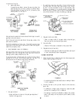
This boiler is equipped with a manual reset protector switch, located
under the small cover on the side of the jacket, fig. 48. This device
provides positive shutdown of the heater in the event of boiler or
system malfunction. Should the surface temperature of the copper
tubing heat exchanger reach 120°C (250°F), the protector switch
will activate, the gas valve will close, the pilot and main burners will
be extinguished. If the protector switch should shut off unit, check
the following conditions:
•
No water in boiler.
•
Restricted water flow through the boiler.
•
Improper wiring (boiler firing without circulator operating).
•
Pump failure.
After correcting failure condition remove the protector switch cover
and push the reset button. The protector switch may be reset after
the coil surface temperature cools to .6°C (1°F).
Содержание Burkay HW-300
Страница 27: ...27 27 27 27 27 FIGURE 21 SCHEMATIC CANADIAN MODELS JUNCTION BOX W 6 TERMINALS...
Страница 63: ...63 63 63 63 63...


