background image

10

CONFINED SPACE

When drawing combustion and dilution air from inside a
conventionally constructed building to a confined space, such a
space shall be provided with two permanent openings, ONE IN
OR WITHIN 12 INCHES (30.5cm) OF THE ENCLOSURE TOP
AND ONE IN OR WITHIN 12 INCHES (30.5cm) OF THE
ENCLOSURE BOTTOM.  Each opening shall have a free area of
at least one square inch per 1000 Btuh (2,225mm

2

/Kw) of the

total input of all appliances in the enclosure, but not less than 100
square inches (645 square cm).

If the confined space is within a building of tight construction, air
for combustion, ventilation, and draft hood dilution must be
obtained from outdoors.  When directly communicating with the
outdoors or communicating with the outdoors through vertical
ducts, two permanent openings, located in the above manner,
shall be provided.  Each opening shall have a free area of not
less than one square inch per 4000 Btuh (8,900mm

2

/Kw) of the

total input of all appliances in the enclosure.  If horizontal ducts
are used, each opening shall have a free area of not less than
one square inch per 2000 Btuh (4,450mm

2

/Kw) of the total input

of all appliances in the enclosure.  For Canadian installations
consult CAN/CSA B149.1-00.

VENT REDUCER

The BTR(C) 250, 251, and 275 models are shipped with an 8" to 6"
diameter flue outlet adapter. Each adapter fits on top of the installed
flue damper.  Use only vent reducers supplied with the unit.  The
venting must comply with the NATIONAL FUEL GAS CODE, ANSI
Z223.1/NFPA 54 and for Canadian installations consult the Natural
Gas and Propane Installation Code CAN/CSA-B149.1.

FIGURE 8

VENTING

 WARNING

THE INSTRUCTIONS IN THIS SECTION ON VENTING MUST
BE FOLLOWED TO AVOID CHOKED COMBUSTION OR
RECIRCULATION OF FLUE GASES.  SUCH CONDITIONS
CAUSE SOOTING OR RISKS OF FIRE AND ASPHYXIATION.

Heater must be protected from freezing downdrafts.

Remove all soot or other obstructions from the chimney that will
retard a free draft.

Type B venting is recommended with these heaters. See table 3
TECHNICAL DATA VENTING.

This water heater must be vented in compliance with all local
codes, the current edition of the National Fuel Gas Code (ANSI-
Z223.1) and with the Category I Venting Tables.

In Canada, venting shall conform to the requirements of the current
Natural Gas and Propane Installation Code CAN/CSA-B149.1
installation code.

If any parts of the vent system are exposed to ambient
temperatures below 35 degrees F (2 degrees C) they must be
insulated to prevent condensation.

Do not connect the heater to a common vent or chimney with
solid fuel burning equipment.  This practice is prohibited by
many local  building codes as is the practice of venting gas
fired equipment to the duct work of ventilation systems.

Where a separate vent connection is not available and the vent
pipe from the heater must be connected to a common vent with
an oil burning furnace, the vent pipe should enter the smaller
common vent or chimney at a point above the large vent pipe.
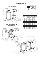
FIGURE 9

MULTIPLE HEATER MANIFOLD

Figure 10 and table 3 should be used for horizontally manifolding
two or more heaters.  Also see MULTIPLE-UNIT INSTALLATIONS
of MECHANICAL VENTING section for induced draft applications.

FIGURE 10

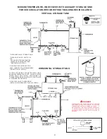
WATER LINE CONNECTIONS

This manual provides detailed installation diagrams (see pages
16-22 of this manual) for typical methods of application for the
water heaters.

The water heater may be installed by itself, or with a separate
storage tank, on both single and two-temperature systems.
When used with a separate storage tank, the circulation may be
either by gravity or by means of a circulating pump.  When a
circulating pump is used it is important to note that the flow rate
should be slow so that there will be a minimum of turbulence
inside the heater.

Содержание BTR 120

Страница 1: ...nnessee Waltz Parkway Ashland City TN 37015 Phone 800 527 1953 Fax 800 433 2515 www hotwater com CAUTION TEXT PRINTED OR OUTLINED IN RED CONTAINS INFORMATION RELATIVE TO YOUR SAFETY PLEASE READ THOROU...

Страница 2: ...3 4 59 00 8 30 25 1 50 2 00 2 00 1 50 2 00 2 00 760 Lbs 874 Lbs 114 kW Hr 379 L 192 cm 12 cm 171 cm 148 cm 68 cm 58 cm 3 4 150 cm 20 cm 77 cm 1 50 2 00 2 00 1 50 2 00 2 00 345 Kg 396 Kg BTRC MODELS 1...

Страница 3: ...1031 957 BTR 390 000 BTUH 100 Gal 80 1293 970 776 646 554 485 431 388 353 323 298 277 400 114 Kw Hr 379 L 4894 3671 2936 2447 2097 1835 1631 1468 1335 1224 1129 1049 TABLE 1D HEATER PERFORMANCE DATA B...

Страница 4: ...ooting Guide 33 Operational Checklist 34 Limited Warranty 35 Page Page FOREWORD These designs comply with ANSI Z21 10 3 CSA 4 3 as an automatic circulating or automatic storage tank type water heater...

Страница 5: ...explosive and heavier than air It collects first in the low areas making its odor difficult to detect at nose level If LP gas is present or even suspected do not attempt to find the cause yourself Go...

Страница 6: ...or operation at altitudes other than that specified on the heater rating plate is not permitted The input reduction is primarily achieved by reducing the size of the main burner orifices To do this th...

Страница 7: ...AUTOMATIC OPERATION and HOLD OPEN DAMPER For normal operation the switch should be in the AUTOMATIC OPERATION position If there is a problem with the damper the Service Switch can be placed in the HOL...

Страница 8: ...g must be a continuous run no joints and retain the 6 16cm clearance unless an approved reducing thimble is used The National Sanitation Foundation also recommends circulation of 180 F 82 C water Wher...

Страница 9: ...NAIR CONTAMINATIONTHATMAYBE HAZARDOUS TOLIFE SUCHACONDITIONOFTENWILLRESULTINAYELLOW LUMINOUSBURNERFLAME CAUSINGCARBONINGORSOOTING OF THE COMBUSTION CHAMBER BURNERS AND FLUE TUBES AND CREATESARISK OFAS...

Страница 10: ...S OF FIRE AND ASPHYXIATION Heater must be protected from freezing downdrafts Remove all soot or other obstructions from the chimney that will retard a free draft Type B venting is recommended with the...

Страница 11: ...BTR C 180 197 198 199 200 Input 180 000 190 000 199 000 Btuh Total Vent Height Feet Draft Hood 6 6 8 10 15 20 30 50 100 Input Btuh Rise Vent Connector Diameter in inches 180 000 1 Ft 8 8 8 8 8 7 7 7...

Страница 12: ...10 10 10 8 8 8 Number of Combined Input Heaters in Thousands of Btuh Manifold Common Vent Diameter 2 610 14 14 12 12 12 10 10 10 3 915 16 16 16 14 14 12 12 12 4 1220 18 18 16 16 16 14 14 12 MODEL BTR...

Страница 13: ...used in conjunction with this appliance shall also be installed with a properly sized rated and approved combination temperature ANSI and pressure ASME relief valve s WARNING THE PURPOSE OF RELIEF VA...

Страница 14: ...AND CERTIFIED FOR GAS SERVICE BEFOREATTACHING THE GAS LINE BE SURE THATALL GAS PIPE IS CLEAN ON THE INSIDE TO TRAP ANY DIRT OR FOREIGN MATERIAL IN THE GAS SUPPLY LINE A DIRT LEG SOMETIMES CALLED SEDIM...

Страница 15: ...SUPPLY PRESSURE TESTING EXCEEDING 1 2 PSIG 3 5 kPa GAS SUPPLY LINE MUSTBE CAPPED WHEN DISCONNECTED FROM THE HEATER FOR TEST PRESSURES OF 1 2 PSIG 3 5 kPa OR LESS THE APPLIANCE NEED NOT BE DISCONNECTED...

Страница 16: ...ULD NOT EXCEED SAFE USE TEMPERATURE AT FIXTURES SEE WATER TEMPERATURE CONTROLWARNING ON PAGE 27 IF HIGHER PREHEAT TEMPERATURESARE NECESSARY TO OBTAINADEQUATE BOOSTER OUTPUT ADD AN ANTI SCALD VALVE FOR...

Страница 17: ...MUST BE CLOSED ON DURING THERINSEOPERATIONANDOPEN OFF WHENDISHWASHER IS NOT OPERATING OR WHEN ON LONG STANDBY NOTE 2 INSTALL LINE TEMPERATURE CONTROL IN AN UNINSULATED TEE BEYOND THE DISHWASHING MACH...

Страница 18: ...wn in the installation diagrams on the following pages are typical TWO TEMPERATURE TWO HEATERS ONE PRE HEATER ONE BOOSTER HEATER WITH OR WITHOUT BUILDING RECIRCULATION The discharge opening of the tem...

Страница 19: ...OTE 3 ADJUST PLUG COCK SO THE SANITIZING LOOP FLOW RATE DOES NOT CAUSE UNNECESSARY TURBULENCE IN THE TANK PIPE RELIEF VALVE TO OPEN DRAIN INSTALL IN ACCORDANCE WITH LOCAL CODES CIRCULATING RETURN LINE...

Страница 20: ...ERS WITH MIXING VALVE TWO PRE HEATERS WITH BOOSTER HEATER DANGER TEMPERATURE SETTING SHOULD NOT EXCEED SAFE USE TEMPERATURE AT FIXTURES SEE WATER TEMPERATURE CONTROL WARNING ON PAGE 27 IF HIGHER PREHE...

Страница 21: ...STER OUTPUT ADD AN ANTI SCALD VALVE FOR HOT WATER SUPPLIED TO FIXTURES PIPE RELIEF VALVE TO OPEN DRAIN WHEN USING AN A O SMITH T 140 200 350 OR 400 STORAGE TANK USE LOWER 3 4 OPENING FOR TANK TEMPERAT...

Страница 22: ...OD A BTR MODELS BTRC MODELS 120 69 75 177cm 69 75 177cm 154 73 00 185cm 73 00 185cm 180 67 50 171cm 70 50 179cm 197 75 00 192cm 81 50 207cm 198 75 00 192cm N A 199 67 50 171cm 70 50 179cm 200 72 00 18...

Страница 23: ...ete instructions MULTIPLE UNIT INSTALLATIONS For multiple unit installations contact A O Smith Water Products Company Technical Support Center at 1 800 527 1953 In Canada contact A O Smith Enterprises...

Страница 24: ...AVOID RISK OF FIRE OR EXPLOSION PURGE DISCHARGE MUST NOT ENTER CONFINEDAREAS OR SPACES WHERE IGNITION CAN OCCUR THE AREA MUST BE WELL VENTILATED AND ALL SOURCES OF IGNITION MUSTBE INACTIVATED OR REMOV...

Страница 25: ...25 FOR NATURAL GAS MODELS...

Страница 26: ...26 FOR PROPANE GAS MODELS...

Страница 27: ...e water temperature is controlled by a thermostat Fig 3 which has two sensing elements One sensor is located near the top of the tank and the other is near the center The thermostat is set in the lowe...

Страница 28: ...MAINTENANCE CHECK THE PILOT At least once a year check the pilot burner fig 15 and the main burner fig 16 for proper operation Refer to the following pilot and main burner sections PILOT BURNER For a...

Страница 29: ...pressure gauge or a manometer to the gauge port and refer to Table 5 for correct manifold pressure 2 Use this formula to clock the meter Be sure that other gas consuming appliances are not operating...

Страница 30: ...he heater and replacement of the factory installed magnesium anodes with aluminum anodes may correct the condition Occasionally water softener companies recommend removal of heater anodes for odor rea...

Страница 31: ...screws securing tank cleanout plate and remove plate 4 Remove lime scale or sediment using care not to damage the glass lining 5 Inspect cleanout plate gasket if new gasket is required replace with A...

Страница 32: ...e replaced TROUBLESHOOTING IGNITION MODULE SYSTEM Before calling your service agent the following checklist should be examined to eliminate obvious problems from those requiring replacement or servici...

Страница 33: ...Blown fuse or circuit breaker 5 Disconnect switch off 6 Harness not plugged into appliance receptacle A FLUE DAMPER OPEN OR OPENING Unit is calling for heat and damper disc should be in vertical posi...

Страница 34: ...slower Call serviceman Check gas input If incorrect adjust gas pressure or replace main burner orifice Draft hood not installed or Call serviceman Install draft hood or baffles as one or more flue ba...

Страница 35: ...e heater s and operational at all times The relief valve installed on the heater is not an acceptable method 4 SERVICE AND REPAIR EXPENSES Under the limited warranty the warrantor will provide only a...

Страница 36: ...36 500 Tennessee Waltz Parkway Ashland City TN 37015 Phone 800 527 1953 Fax 800 433 2515 www hotwater com...

Отзывы: