background image

8

AND ONE IN OR WITHIN 12 INCHES (30.5cm) OF THE
ENCLOSURE BOTTOM.  Each opening shall have a free area of
at least one square inch per 1000 Btuh (2,225mm

2

/kW)of the

total input of all appliances in the enclosure, but not less than
100 square inches (645 square cm).
If the confined space is within a building of tight construction, air
for combustion, ventilation, and drafthood dilution must be
obtained from outdoors.  When directly communicating with the
outdoors or communicating with the outdoors through vertical
ducts, two permanent openings, located in the above manner,
shall be provided.  Each opening shall have a free area of not
less than one square inch per 4000 Btuh (550mm

2

/kW) of the

total input of all appliances in the enclosure.  If horizontal ducts
are used, each opening shall have a free area of not less than
one square inch per 2000 Btuh (1102mm

2

/kW) of the total input

of all appliances in the enclosure.

VENTING

 WARNING

THE INSTRUCTIONS IN THIS SECTION ON VENTING MUST
BE FOLLOWED TO AVOID CHOKED COMBUSTION OR
RECIRCULATION OF FLUE GASES.  SUCH CONDITIONS
CAUSE SOOTING OR RISKS OF FIRE AND ASPHYXIATION.

Heater must be protected from freezing downdrafts.

Remove all soot or other obstructions from the chimney that will
retard a free draft.

Type B venting is recommended with these heaters. For typical
venting application see TECHNICAL DATA VENTING on pages 9
and 10.

This water heater must be vented in compliance with all local
codes, the current revision of the National Fuel Gas Code
(ANSI-Z223.1) and with the Category I Venting Tables.

If any part of the vent system are exposed to ambient
temperatures below 40°F (5°C) it must be insulated to prevent
condensation.

The following steps shall be followed with each appliance
connected to the venting system placed in operation, while any
other appliances connected to the venting system are not in
operation.

1.  Seal any unused openings in the venting system.
2. Inspect the venting system for proper size and horizontal pitch,

as required in the National Fuel Gas Code, ANSI Z223.1.
Determine that there is no blockage or restriction, leakage,
corrosion and other deficiencies which could cause an unsafe
condition.

3. So far as is practical, close all building doors and windows

and all doors between the space in which the water heater(s)
connected to the venting system are located and other spaces
of the building.  Turn on all appliances not connected to the
venting system.  Turn on all exhaust fans, such as range
hoods and bathroom exhausts, so they shall operate at

maximum speed. Close fireplace dampers.

4.  Follow the lighting instruction.  Place the water heater being

inspected in operation.  Adjust thermostat so appliance shall
operate continuously.

5.  After it has been determined that each appliance connected

to the venting system properly vents when tested as outlined
above, return doors, windows, exhaust fans, fireplace
dampers and any other gas burning appliance to their
previous conditions of use.

6.  If improper venting is observed during any of the above tests,

the venting system must be corrected.

 WARNING

FAILURE TO CORRECT BACK DRAFTS MAY CAUSE AIR
CONTAMINATION AND UNSAFE CONDITIONS.

• If the back draft cannot be corrected by the normal method or

if a suitable draft cannot be obtained, a blower type flue gas
exhauster must be employed to assure proper venting and
correct combustion.

• Do not connect the heater to a common vent or chimney with

solid fuel burning equipment.  This practice is prohibited by
many local  building codes as is the practice of venting gas
fired equipment to the duct work of ventilation systems.


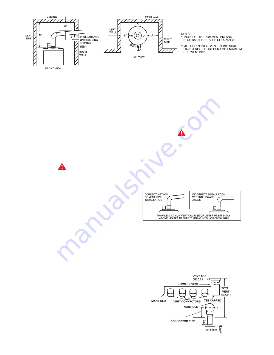
FIGURE 7

• Where a separate vent connection is not available and the

vent pipe from the heater must be connected to a common
vent with an oil burning furnace, the vent pipe should enter
the smaller common vent or chimney at a point above the
large vent pipe.

MULTIPLE HEATER MANIFOLD

Figure 8 and tables on pages 9 and 10 should be used for
horizontally manifolding two or more heaters.


FIGURE 8

ILLUSTRATION OF MINIMUM COMBUSTIBLE CLEARANCES IN AN ALCOVE - FIGURE 6

Содержание BTI 120

Страница 1: ...000 Printed in U S A 0803 SUPERSEDESPARTNO 194780 000 ADIVISION OFA O SMITH CORPORATION McBEE SOUTH CAROLINA USA www hotwater com CAUTION TEXT PRINTED OR OUTLINED IN RED CONTAINS INFORMATION RELATIVE...

Страница 2: ...96 91 88 82 35 269 LPH 1209 1088 870 806 725 622 604 544 484 435 403 396 363 345 335 311 BTI 154 154 000 81 80 GPH 410 369 295 273 246 211 205 184 164 148 137 134 123 117 113 105 45 307 LPH 1551 1396...

Страница 3: ...ent Parts 29 Sequence of Operation Flow Chart 30 Operational Checklist 31 Limited Warranty 32 Page Page FOREWORD These designs comply with ANSI Z21 10 3 as an automatic circulating or automatic storag...

Страница 4: ...FOR SAFE OPERATION LIQUID PETROLEUM MODELS Water heaters for propane or liquefied petroleum gas LPG are different from natural gas models A natural gas heater will not function safely on LP gas and no...

Страница 5: ...ements Also due to the input rating reduction required at high altitudes the output rating of the appliance is also reduced and should be compensated for in the sizing of the equipment for application...

Страница 6: ...es are high a water pressure reducing or flow regulating control valve should be used in 1800 F 82 C line to the dishwashing machine and should be adjusted to deliver water between these limits The Na...

Страница 7: ...51mm 2 51mm 12 305mm BTI 250 A 2 51mm 2 51mm 2 51mm 12 305mm BTI 275 A 2 51mm 2 51mm 2 51mm 12 305mm BTI 310 A 3 76mm 3 76mm 3 76mm 12 305mm BTI 366 A 3 76mm 3 76mm 3 76mm 12 305mm BTI 400 A 3 76mm 3...

Страница 8: ...nspect the venting system for proper size and horizontal pitch as required in the National Fuel Gas Code ANSI Z223 1 Determine that there is no blockage or restriction leakage corrosion and other defi...

Страница 9: ...ches 154 000 1 Ft 6 6 6 6 6 6 6 6 154 000 2 Ft 6 6 6 6 6 6 6 6 154 000 3 Ft 6 6 6 6 6 6 6 6 Number of Combined Input BTI 154 Heaters in Thousands of Btu hr Manifold and Common Vent Diameter Inches 2 3...

Страница 10: ...I 310 Input 310 000 Btu hr Total Vent Height Feet Vent Connector Size 6 inches 6 8 10 15 20 30 50 100 Input Btu hr Rise Vent Connector Diameter Inches 310 000 1 Ft 9 8 8 8 7 7 6 6 310 000 2 Ft 8 8 8 7...

Страница 11: ...system as a means of detecting the temperature of the outlet water supply RELIEF VALVE This water heater is equipped with a combination temperature pressure relief valve that complies with the standa...

Страница 12: ...s resistant to the action of liquefied petroleum gases BEFORE PLACING THE HEATER IN OPERATION CHECK FOR GAS LEAKAGE Use soap and water solution or other material acceptable for the purpose in locating...

Страница 13: ...iction AN ELECTRICAL GROUND IS REQUIRED TO REDUCE RISK OF ELECTRICAL SHOCK OR POSSIBLE ELECTROCUTION If any of the original wire as supplied with the appliance must be replaced use only type 1050 C th...

Страница 14: ...RATURE CONTROL WARNING ON PAGE 23 IF HIGHER PREHEAT TEMPERATURES ARE NECESSARY TO OBTAIN ADEQUATE BOOSTER OUTPUT ADD AN ANTI SCALD VALVE FOR HOT WATER SUPPLIED TO FIXTURES GENERAL The type size and lo...

Страница 15: ...OULD NOT EXCEED SAFE USE TEMPERATUREAT FIXTURES SEE WATERTEMPERATURE CONTROL WARNING ON PAGE 25 IF HIGHER PREHEAT TEMPERATURES ARE NECESSARYTO OBTAINADEQUATE BOOSTER OUTPUT ADDANANTI SCALD VALVE FOR H...

Страница 16: ...OGGLESWITCHMUSTBECLOSED ON DURING THERINSEOPERATIONANDOPEN OFF WHENDISHWASHER IS NOTOPERATING OR WHEN ON LONG STANDBY NOTE 2 INSTALLLINETEMPERATURECONTROLINANUNINSULATED TEEBEYONDTHEDISHWASHINGMACHINE...

Страница 17: ...s shown in the installation diagrams on the following pages are typical TWO TEMPERATURE TWO HEATERS ONE PRE HEATER ONE BOOSTER HEATER WITH OR WITHOUT BUILDING RECIRCULATION The discharge opening of th...

Страница 18: ...NOTE 3 ADJUST PLUG COCK SO THE SANITIZING LOOP FLOW RATE DOES NOT CAUSE UNNECESSARYTURBULENCEIN THETANK PIPE RELIEF VALVE TO OPEN DRAIN INSTALL IN ACCORDANCE WITH LOCAL CODES CIRCULATING RETURN LINE...

Страница 19: ...ERS WITH MIXING VALVE TWO PRE HEATERS WITH BOOSTER HEATER DANGER TEMPERATURE SETTING SHOULD NOT EXCEED SAFE USE TEMPERATURE AT FIXTURES SEE WATER TEMPERATURE CONTROL WARNING ON PAGE 25 IF HIGHER PREHE...

Страница 20: ...TER OUTPUT ADD AN ANTI SCALD VALVE FOR HOT WATER SUPPLIEDTO FIXTURES PIPE RELIEF VALVE TO OPEN DRAIN WHEN USING AN A O SMITH T 140 200 350 OR 400 STORAGE TANK USE LOWER 3 4 OPENING FOR TANK TEMPERATUR...

Страница 21: ...154 70 BTI 180 70 BTI 199 70 BTI 200 A 72 BTI 250 A 72 BTI 275 A 72 BTI 310 A 73 BTI 366 A 73 BTI 400 A 73 MANIFOLD KITS TWO UNIT MANIFOLD KIT PART NO 195686 THREE UNIT MANIFOLD KIT PART NO 195687 FO...

Страница 22: ...filled with water and all air is expelled FILLING 1 Close the heater drain valve by turning handle clockwise 2 Open a nearby hot water faucet to permit the air in the system to escape 3 Fully open th...

Страница 23: ...d then shuts off power to the Silicon Nitride Ignitor 11 From the time the Silicon Nitride Ignitor s power is shut off the Ignition Control Board waits 3 more seconds to monitor the Flame Sensor 12 If...

Страница 24: ...tes to clear out any gas If you then smell gas STOP Follow B in the safety information above on this label If you don t smell gas go on to the next step 7 Turn gas control knob counterclockwise to ON...

Страница 25: ...that attach to faucets to limit hot water temperatures Contact a licensed plumber or the local plumbing authority The water temperature is controlled by a thermostat fig 3 which has two sensing eleme...

Страница 26: ...ncrease gas pressure and input rate Counterclockwise to decrease gas pressure and input rate 4 Clock the meter as in step 2 above 5 Repeat steps 3 and 4 until the specified input rate is achieved 6 Tu...

Страница 27: ...rs on the heater will usually be damaged when removed New pipe collars will insure that the seal is such as to prevent leakage of flue products when properly installed NOTE Anode rod inspection may ne...

Страница 28: ...lied with the kit 2 Remove the container s cap and cut the plastic membrane located in the 3 4 IPT opening in the cap Take care to not damage the threads 3 Find the 3 4 male adapter apply teflon tape...

Страница 29: ...hat incorporates a diagnostic system to assist in troubleshooting the appliance The indicator codes on the ignition module are as follows 1 flash System lockout retries or cycles exceeded 2 flashes Pr...

Страница 30: ...engages Prover Switch Ignition Control Board provides power to Silicon Nitride Ignitor Silicon Nitride Ignitor warms up for 20 seconds Ignition Control Board opens Gas Valve Ignition Control Board sh...

Страница 31: ...metallic sounds Expansion and contraction normal Pounding Air chambers in piping have Drain piping system and refill become waterlogged Heater must be off while this is being done Combustion noises T...

Страница 32: ...heater is connected to unless an effective method of controlling thermal expansion is also installed at the heater s and operational at all times The relief valve installed on the heater is not an acc...

Отзывы: