A.O. Smith AHPM-270 Скачать руководство пользователя страница 19

15

2.  Heat transfer compound (paste) such as Honeywell part 

number 107408 or equivalent.

3. 

Electrical switch lock out device - used to secure disconnect 
switches/breaker panels while servicing.

4.  Electronic thermometer including:

• 

Four (4) thermocouple sensors capable of measuring surface 
temperatures on water or refrigerant piping up to 2 
inch diameter.

• 

Two (2) thermocouple sensors capable of measuring 
ambient air temperature.

• 

Temperature range 32°F - 210°F (0°C - 100°C).

5.  Volt-Ohm Multi Meter - capable of measuring:

• 

AC Voltage up to 600 VAC.

• 

DC Voltage up to 24 VDC.

• 

Ohms up to 2,000,000 ohms.

• Continuity.

6.  AC amp meter - capable of measuring:

• 

AC amperage up to 200 amps.

7.  Calculator.    

SERVICE TOOLS

See Qualifications on page 3 regarding regulations and 
certifi cations required under Section 608 of the Clean Air Act 
before servicing the refrigeration circuit.

1.  Refrigeration manifold gauges.

2.  Refrigeration charging scale.

3.  Refrigeration vacuum pump.

4.  Refrigerant recovery machine.

5.  Refrigerant reclamation storage tank.

UNIT PLACEMENT

Whether replacing existing water heating equipment or installing 
the HPWH in new construction, the following critical points 
must be observed: The HPWH unit:

1. 

The HPWH, storage tank and water heater(s) should be located 
in an area where leakage will not result in damage to 
adjacent area or to lower fl oors in the building structure.

2.  The HPWH unit must be level for proper operation. Shim 

the channel type skid base, pad or fl oor as necessary if 
leveling is required.

3.  Should be installed close to the point of major hot water 

usage and power supply.

4.  Should be located so that hot water piping and branch 

circuit wiring will be as short as possible.

MOUNTING FRAME

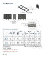
The mounting frame must support the length, width, and 
weight of the HPWH unit. The weight of the HPWH unit must 

be evenly dispersed across the footing channels on the bottom 
of the unit. See Table 1 on page 8 for unit dimensions and 
weights.

Note: 

A qualifi ed engineer should design and size the structural 

components of the mounting frame. Structural channels in a 
fi eld-provided frame should be mounted perpendicular to the 
unit’s footing channels. 
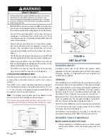
PAD MOUNTING

The HPWH may be pad mounted. Vibration isolator mounts 
MUST BE placed between the unit and the equipment pad to 
prevent mechanical vibration transmitting into the building 
structure. Selection of appropriate vibration isolators should 
be made by a qualified engineer. Unit must be level and 
elevated at least 6” above fl oor to avoid dust and debris from 
entering the unit.

ELECTRICAL CONNECTIONS

CORRECT VOLTAGE AND PHASE

The HPWH units covered by this instruction manual can be 
ordered with multiple power supply voltage and phase 
configurations. Ensure the power supply voltage and phase 
at the job site matches the power supply ratings listed on the 
HPWH rating label BEFORE INSTALLATION BEGINS.

Voltage applied to the HPWH should not vary more than +5% 
to -10% of the voltage requirement listed on the HPWH rating 
label for satisfactory operation.

Energizing the HPWH with the wrong voltage and/or phase 
may cause permanent damage to HPWH components. Damage 
resulting from applying the wrong power supply voltage or 
phase to the HPWH is not covered under the limited warranty.

BRANCH CIRCUIT DISCONNECT SWITCH

The power supply wiring and equipment grounding must be 
installed in accordance with local codes or, in the absence of 
local codes, the National Electrical Code, ANSI/NFPA 70 or the 
Canadian Electrical Code, CSA C22.1.

Install an adequately fused disconnect switch as close to the 
units possible. See unit rating label for maximum fuse size 
(MFS). 

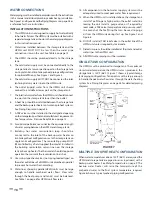
Run the power supply lines from the disconnect to the 
control box at the side panel of the unit. Connect the lines to 
the terminals on input side of power distribution block L1 & 
L2 for single phase and L1, L2 & L3 for three phases. Connect 
ground wire to ground lug.

Содержание AHPM-270

Страница 1: ...ion Manual Series 100 Models AHPM 270 AHPM 540 AHPM 810 AHPM 1080 AHPM 1350 AHPM 1620 AHPM 1890 AHPM 2160 Modular Water Source Commercial Heat Pump Water Heating Systems Certified UL 1995 2015 CSA C22...

Страница 2: ......

Страница 3: ...O MEMBER UNITS 22 MASTER CONTROL UNIT SUPPORT CALL SEQUENCE OF OPERATIONS 22 MEMBER SCREENS 23 SAFE INSTALLATION USE AND SERVICE 1 GENERAL SAFETY INFORMATION 2 PRECAUTIONS 2 GROUNDING INSTRUCTIONS 2 I...

Страница 4: ...DDRESS CONFIGURATION 23 SINGLE UNIT HEAT BANK SCREEN 23 MEMBER SCREEN TERMINOLOGY 24 HOME SCREEN 24 ALARM SCREEN 24 CONFIGURATION SCREEN 24 STOP SCREEN 24 IP CONFIGURATION 24 MAINTENANCE AND SERVICE 2...

Страница 5: ...hers who install use or service this heat pump water heater All safety messages will generally tell you about the type of hazard what can happen if you do not follow the safety message and how to avoi...

Страница 6: ...External fire 2 Damage 3 Running without water GROUNDING INSTRUCTIONS This heat pump water heater must be grounded in accordance with the National Electrical Code and or local codes These must be foll...

Страница 7: ...AGE Thismanualcontainsinstructionsfortheinstallation operation and maintenance of the heat pump water heater HPWH It also contains warnings throughout the manual that you must read and be aware of All...

Страница 8: ...ustomer provided Water Pump circulates water through the condenser Refrigerant leaving the condenser is a medium temperature high pressure liquid It flows through the Liquid Line to the Thermostatic E...

Страница 9: ...Circuit Heated Water Inlet Condenser Heat Exchanger Heated Water Outlet Figure 1 FEATURES COMPONENTS PRODUCT ILLUSTRATION Component Source Water Circuit Source Water Inlet Evaporator Heat Exchanger S...

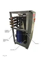
Страница 10: ...6 Thermostatic Expansion Valve TXV Condenser Paddle Wheel Flow Sensor Accumulator Receiver...

Страница 11: ...7 WATER TO WATER CYCLE...

Страница 12: ...H AHPM 270 50 50 277 100 210 000 2 34 36 68 1 150 1 300 AHPM 540 100 100 554 200 414 450 2 64 36 68 2 300 2 600 AHPM 810 150 150 831 300 632 500 2 99 36 68 3 450 3 900 AHPM 1080 200 200 1 108 400 843...

Страница 13: ...st conform to these instructions and all local and national code authority having jurisdiction Costs to diagnose perform service and repair damage caused by installation errors are not covered under t...

Страница 14: ...0 or the Canadian Electrical Code CSA C22 1 Voltage applied to the HPWH should not vary more than 5 to 10 of the voltage requirement listed on the HPWH rating label for satisfactory operation TABLE 2...

Страница 15: ...e heat pump water heaters are two wire circuits Three phase heaters are three wire circuits In addition to the foregoing a grounded conductor is required Not more than three conductors in raceway cabl...

Страница 16: ...ion to using the lowest possible temperature setting that satisfies the demand of the application a Mixing Valve should be installed upstream from the building fixtures or at the hot water taps to fur...

Страница 17: ...sistance in sizing of a temperature and pressure relief valve Follow the storage tank manufacturer s instructions regarding the proper installation of these products TANK SELECTION The HPWH unit is no...

Страница 18: ...omponents are not moisture tolerant Note The limited warranty does not cover damage to the unit or controls due to negligence during storage The pictures may appear different than your actual unit all...

Страница 19: ...g channels on the bottom of the unit See Table 1 on page 8 for unit dimensions and weights Note A qualified engineer should design and size the structural components of the mounting frame Structural c...

Страница 20: ...ntrolled by a field supplied thermostat installed in the building recirculation return line near the storage tank or back up heater The thermostat should stop pump operation the moment the recirculati...

Страница 21: ...line on the HPWH to help prevent scale build up in the heat exchanger Service costs to clear blockages from the HPWH unit s heat exchanger due to debris are not covered under the limited warranty ELEC...

Страница 22: ...ey on the Touchscreen Monitor the refrigerant pressure hot water in and out temperatures and cold water in and out temperatures Itmaybehelpfultorecordtheoperatingdatainitiallyevery10 to15minutesjustto...

Страница 23: ...ince they will always start and run in the proper direction Three phase compressors will rotate in either direction depending upon phasing of the power to L1 L2 and L3 Since there is a 50 50 chance of...

Страница 24: ...inimum of water piping between the HPWH and the water system or tank Throttling should be done in small increments no more than 1 8 turn of the valve handle at a time The HPWH must be allowed to run f...

Страница 25: ...TER PANEL ALARM SCREEN MASTER PANEL CONFIGURATION SCREEN MASTER SCREEN TERMINOLOGY HOME SCREEN LP Low Pressure indicates the suction line pressure on the low side of the system HP High Pressure indica...

Страница 26: ...pDiff Temperature Difference sets the difference below the setpoint where the master will give a call for members to run SAVE button Saves the Tank Diff Set and System Timer parameters Master IP Addre...

Страница 27: ...ME SCREEN OPERATING AS A SINGLE UNIT IN DEFROST SINGLE UNIT HOME SCREEN DISPLAYING ALARM SINGLE UNIT ALARM SCREEN SINGLE UNIT PIPE CONFIGURATION SCREEN SINGLE UNIT TANK CONFIGURATION SCREEN SINGLE UNI...

Страница 28: ...n short cycling OUTLET FLOW indicates if the unit has alarmed out on condenser water flow Evap Flow indicates if the evaporator has flow M PROTECTION indicates if the unit has alarmed out on motor pro...

Страница 29: ...l from the insulation using a vacuum device with a HEPA filter 99 97 efficient at 0 3 micron particles Be careful not to tear the insulation during the cleaning procedure 4 Apply the microbial cleanin...

Страница 30: ...ould be 8 F to 12 F 4 4 C to 6 7 C BRAZE PLATE CLEANING INSTRUCTIONS In some applications the heat exchanger may be subjected to severe fluid conditions including high temperature hard water condition...

Страница 31: ...d Shut off valves are partially closed Thermostat setting should not exceed 160 F Keep heat pump off until room temperature is back in operating range Low water ow corrections Replace unit pump Reduc...

Страница 32: ...K ISOLATION VALVE CIRCULATING PUMP TEMPERATURE GAUGE WYE STRAINER TEMP PRESS RELIEF VALVE FLUSH VALVE PIPING WIRING ONLY USE BOTTOM LOWER CONNECTION IF TANK HAS TWO THERMOWELL HP WATER HEATER THERMAL...

Страница 33: ...TION VALVE CIRCULATING PUMP TEMPERATURE GAUGE WYE STRAINER TEMP PRESS RELIEF VALVE FLUSH VALVE PIPING WIRING ONLY USE BOTTOM LOWER CONNECTION IF TANK HAS TWO HP WATER HEATER THERMOWELL THERMAL STORAGE...

Страница 34: ...GAUGE WYE STRAINER TEMP PRESS RELIEF VALVE FLUSH VALVE PIPING WIRING ONLY USE BOTTOM LOWER CONNECTION IF TANK HAS TWO THERMOWELL HP WATER HEATER HP WATER HEATER MASTER CONTROL PANEL RECOMMENDED FOR MU...

Страница 35: ...HECK VALVE EXPANSION TANK ISOLATION VALVE CIRCULATING PUMP TEMPERATURE GAUGE WYE STRAINER TEMP PRESS RELIEF VALVE FLUSH VALVE PIPING WIRING HP WATER HEATER THERMOWELL THERMAL STORAGE COLD WATER SUPPLY...

Страница 36: ...SINGLE HEATER MIXING VALVE CHECK VALVE EXPANSION TANK ISOLATION VALVE CIRCULATING PUMP TEMPERATURE GAUGE WYE STRAINER TEMP PRESS RELIEF VALVE FLUSH VALVE PIPING WIRING SOURCE WATER SUPPLY SOURCE WATE...

Страница 37: ...HEATER REVERSE RETURN MIXING VALVE CHECK VALVE EXPANSION TANK ISOLATION VALVE CIRCULATING PUMP TEMPERATURE GAUGE WYE STRAINER TEMP PRESS RELIEF VALVE FLUSH VALVE PIPING WIRING SOURCE WATER SUPPLY SOUR...

Страница 38: ...en the heat pump water heater is installed in accordance with local plumbing and building codes ordinances and regulations the warrantor s printed instructions provided with it and good industry pract...

Страница 39: ...35 500 Tennessee Waltz Parkway Ashland City TN 37015 Technical Support 1 833 447 3201 www hotwater com...

Страница 40: ...36 Service Log Issue Description Date Servicer...

Страница 41: ...Service Log Issue Description Date Servicer 37...

Страница 42: ...Notes 38...

Страница 43: ......

Страница 44: ......

Отзывы: