


12
CLOSED WATER SYSTEMS
Water supply systems may, because of code requirements or
such conditions as high line pressure, among others, have
installed devices such as pressure reducing valves, check
valves, and back fl ow preventers. Devices such as these cause
the water system to be a closed system.
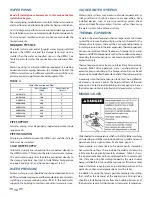
THERMAL EXPANSION
As water is heated, it expands (thermal expansion). In a closed
system the volume of water will grow when it is heated. As the
volume of water grows there will be a corresponding increase
in water pressure due to thermal expansion. Thermal expansion
can cause premature failure (leakage) of storage tanks, water
heaters and HPWH components such as the condenser. Leakage
caused by thermal expansion is not covered under the HPWH
limited warranty.
Thermal expansion can also cause intermittent Temperature-
Pressure Relief Valve operation: water discharged due to
excessive pressure build up. The Temperature-Pressure Relief
Valve is not intended for the constant relief of thermal expansion.
A properly sized thermal expansion tank must be installed on
all closed systems to control the harmful eff ects of thermal
expansion. Contact a local plumbing service agency to have a
thermal expansion tank installed on all closed water systems.
MIXING VALVES
Water heated to a temperature which will satisfy clothes washing,
dish washing, and other sanitizing needs can scald and cause
permanent injury upon contact. See Table 5, page 13.
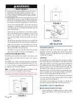
Some people are more likely to be permanently injured by
hot water than others. These include the elderly, children, the
infi rm and the physically/mentally disabled. Table 5 shows
the approximate time-to-burn relationship for normal adult
skin. If anyone using hot water provided by the water heater
being installed fi ts into one of these groups or if there is a local
code or state law requiring a certain water temperature at the
point of use, then special precautions must be taken.
In addition to using the lowest possible temperature setting
that satisfi es the demand of the application a Mixing Valve
should be installed upstream from the building fi xtures or at
the hot water taps to further reduce system water temperature.
WATER PIPING
Read all installation requirements in this manual before
installation begins
.
The water piping installation must conform to these instructions
and to all local and national code authority having jurisdiction.
Costs to diagnose, perform service and repair damage caused
by installation errors are not covered under the limited warranty.
Costs to correct installation errors are not covered under the
limited warranty.
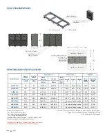
MINIMUM PIPE SIZE
The inlet (return) and outlet (supply) water piping installed
between the HPWH unit and the storage tank must not be
smaller than the water connection sizes on the HPWH. See
Table 4, below, for water line connection sizes and water fl ow
rates.
Water line sizing is a critical installation requirement. Installing
undersized water piping between the storage tank and the
HPWH unit will cause insuffi
cient water fl ow and will have an
adverse impact on performance and equipment life.
TABLE 4
PIPE SUPPORT
All water piping must be properly supported per local code
requirements.
PIPE INSULATION
All piping installed between the HPWH unit and the storage
tank must be insulated.
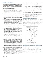
COLD WATER SUPPLY
Cold water supply lines should not be connected directly to
the HPWH inlet or T fi tted into the inlet (return) water piping.
The cold water supply lines should be connected directly to
the storage tank only. See Inlet & Outlet Water Temperature
on page 9 and Figure 7 and Figure 8 on pages 16 & 17.
WATER PRESSURE
System water pressure should be maintained between 40 and
60 PSI. Local code may require, and the manufacturer recommends,
installing a pressure reducing valve (PRV) in the cold water
supply to the building to maintain consistent water pressure.
Water Connection and Flow
Unit
Water Flow Rate
(GPM)
Connection Size
(Inches)
AHPM-270
50
2”
AHPM-540
100
2”
AHPM-810
150
2”
AHPM-1080
200
2”
AHPM-1350
250
2”
AHPM-1620
300
2”
AHPM-1890
350
2”
AHPM-2160
400
2”
Содержание AHPM-270
Страница 2: ......
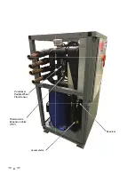
Страница 10: ...6 Thermostatic Expansion Valve TXV Condenser Paddle Wheel Flow Sensor Accumulator Receiver...
Страница 11: ...7 WATER TO WATER CYCLE...
Страница 39: ...35 500 Tennessee Waltz Parkway Ashland City TN 37015 Technical Support 1 833 447 3201 www hotwater com...
Страница 40: ...36 Service Log Issue Description Date Servicer...
Страница 41: ...Service Log Issue Description Date Servicer 37...
Страница 42: ...Notes 38...
Страница 43: ......
Страница 44: ......


