- Elektroanschlüsse dürfen nur von einer Elektro-
Fachkraft durchgeführt werden!
- Die bauseitige Elektroinstallation muss den
jeweiligen Schutzbestimmungen entsprechen
(230/240 V AC, 50/60 Hz)!
- Vor allen Arbeiten am Antrieb ist der Akku-
Stecker aus dem Akku-Pack zu ziehen!
- Fremdspannung an den Anschlussklemmen der
Steuerung führt zu einer Zerstörung der
Elektronik!
- Zur Vermeidung von Störungen ist darauf zu
achten, dass die Akku-Leitungen (24V DC) in
einem getrennten Installations-System zu
anderen Versorgungs-Leitungen (230 V AC) zu
verlegen sind!
Zum Anschluss von Zusatzkomponenten muss das
Sichtfenster abgenommen werden. Die Klemmen, an
die Zusatzkomponenten wie potentialfreie Innen- und
Außentaster, Ausschalter oder Schlupftürkontakt
angeschlossen werden, führen nur eine ungefährliche
Kleinspannung von max. 30 V DC.
Alle
Anschlussklemmen sind mehrfach belegbar,
jedoch max.1x2,5mm
2
. Vor dem Anschluss ist in
jedem Fall der Akku-Stecker zu ziehen!
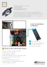
3.5.1 Programmieren der Handsender
Der mitgelieferte Handsender muss auf den
eingebauten Funkempfänger des Antriebs wie folgt
programmiert werden:
1) Persönlichen Code am Handsender einstellen.
2) Schwarze Taste
und anschließend zusätzlich die
weiße Bedientaste auf der Steuerelektronik drücken
und beide Tasten solange gedrückt halten (ca. 1Sek.)
bis die Antriebsbeleuchtung in einen Blinkintervall
von 1x Blinken wechselt. Nun beide Tasten
wieder los
lassen.
3) Handsendertaste solange drücken (ca. 2 Sek.), bis
das Blinken der Antriebsbeleuchtung beendet ist.
Der Code ist nun eingelernt und der eingebaute
Empfänger ist betriebsbereit. Anschließend eine
Funktionsprüfung durchzuführen.
3.5.2 Anschluss externer "Impuls"-Taster zum
Auslösen oder Stoppen von Torfahrten
Ein oder mehrere Taster mit Schließerkontakten
(potentialfrei) wie z.B. Innen- oder Schlüsseltaster wird
oder werden (dann parallel) an den Klemmen
21
(Impulseingang) und
20
(0V) angeschlossen (siehe
Bild 12).
3.5.3 Anschluss eines Ausschalters oder eines
Schlupftürkontaktes (dieser muss zwangsöffnend
sein) zum Anhalten oder/und Ausschalten des
Antriebes (Halt- bzw. Not-Aus-Kreis)
Ein Ausschalter mit Öffnerkontakten (potentialfrei) wird
wie folgt angeschlossen (siehe Bild 13):
1) Den potentialfreien Öffnerkontakt an den Klemmen
12
(Halt- bzw. Not-Aus-Eingang) und
13
anschließen.
2) DIP-Schalter
1)
auf
Off
stellen.
Hinweis
Durch das Öffnen des Kontaktes werden eventuelle
Torfahrten sofort angehalten und dauerhaft unter-
bunden. Die Antriebsbeleuchtung signalisiert den
Pulscode 1x blinken.
3.5.4 DIP-Schalterfunktionen
DIP 1 Halt- bzw. Not-Aus-Kreis
ON
= Eingang nicht aktiv
OFF
= Eingang aktiviert
DIP 2
keine Funktion
DIP 3
keine Funktion
DIP 4
bestimmt den
Softlauf bei "Tor - ZU"
ON
= Softlauf für Kipptore ( 30% Kraft / 30%
Geschwindigkeit )
OFF
= Softlauf für Sectionaltore und sehr schwere
Kipptore ( 50% Kraft / 50% Geschwindigkeit)
DIP 5 Kurzrücklauf bei "Tor -ZU"
ON
= Kurzrücklauf ein
OFF
= Kurzrücklauf aus
3.6 Hinweise für den Betrieb des Garagentorantriebes
Hinweis
Die ersten Funktionsprüfungen sowie das Programmieren
oder Erweitern der Fernsteuerung sollten grund-
sätzlich im Inneren der Garage durchgeführt werden.
Betreiben Sie den Garagentorantrieb nur, wenn Sie
den Bewegungsbereich des Tores einsehen können!
Warten Sie so lange bis das Tor zum Stillstand
gekommen ist, bevor Sie sich in den Bewegungs-
bereich des Tores begeben!
Vergewissern Sie sich vor der Ein- bzw. Ausfahrt, ob
das Tor auch ganz geöffnet wurde!
ACHTUNG
Handsender gehören nicht in
Kinderhände!
Die Funktion der mechanischen Entriegelung ist
monatlich
zu überprüfen. Die Seilglocke darf nur bei
geschlossenem Tor betätigt werden, sonst besteht die
Gefahr, dass das Tor bei schwachen, gebrochenen
oder defekten Federn oder wegen mangelhaftem
Gewichtsausgleichs schnell zulaufen kann.
ACHTUNG
Nicht mit dem Körpergewicht an die
Seilglocke hängen!
Weisen Sie alle Personen, die die
Toranlage benutzen, in die ordnungs-
gemäße und sichere Bedienung des
Garagentorantriebes ein. Demonstrieren
und testen Sie die mechanische
Entriegelung sowie den Sicherheits-
rücklauf.
Halten Sie dazu das Tor während des Torzulaufes
mit beiden Händen an; die Toranlage sollte sanft
abschalten und den Sicherheitsrücklauf einleiten.
Ebenso muss während des Torauflaufes die
Toranlage sanft abschalten und das Tor stoppen.
!
10.2004 V1.0 / 201_AKKU
22
-
Electrical connections may only be performed by
a skilled electrician!
-
The on-site electrical installation must
comply with the respective safety regulations
(230/240 V AC, 50/60 Hz)!
-
Before working on the opener, always unplug
the battery plug from the battery pack!
-
Applying external voltage to the connection
terminals of the control system will destroy
the electronics!
-
To avoid malfunctions, ensure that the battery
cables (24V DC) are laid in an installation system
that is separate from the other supply lines
(230 V AC)!
When connecting additional components, the inspection
window must be removed. The terminals to which the
accessory components, such as potential-free inside
and outside buttons, off switches or wicket door contacts
are connected only carry a low harmless voltage of
max. 30 VDC .
All connection terminals can be used
simultaneously for multiple accessories, however,
max.1x2.5 mm
2
.
The opener must always be unplugged
from the battery plug before connection!
3.5.1 Programming the remote control
The supplied remote control must be programmed on
the opener's integrated radio receiver as follows:
1) Set the personal code on the remote control.
2) Press the black button and then also the white button
and hold both buttons pressed (approx. 1 sec) until
the door opener light switches starts flashing in
1 flash intervals. Then release both buttons again.
3) Press the remote control button (approx. 2 sec.) until
the opener light stops flashing.
The code is then taught in and the integrated receiver is
ready for operation. Then perform a function test.
3.5.2 Connecting an external "Pulse" button for
triggering or stopping door runs
One or more buttons with NO contacts (potential-
free), e.g. inside or key switches, are connected (in
parallel) to the terminal
21
(pulse input) and
20
(0V)
(see Figure 12).
3.5.3 Connecting an off switch or a wicket door
contact (must have positive opening action) to stop
and/or switch off the opener (stop or emergency
stop circuit)
An off switch with NC contacts (potential-free) is
connected as follows (see Figure 13):
1) Connect the potential-free NC contact to terminals
12
(stop or emergency stop circuit) and
13
.
2) Set DIP switch
1)
to
Off
.
Note
Breaking the contact stops any door movements which
are in progress immediately and permanently prevents
further movements. The opener light issues the flash 1x
pulse code.
Note
Initial function tests as well as the programming or
expansion of the remote control should generally be
carried out inside the garage.
3.5.4 DIP switch functions
DIP 1 Stop or emergency stop circuit
ON
= Input not active
OFF
= Input activated
DIP 2
No function
DIP 3
no function
DIP 4
sets the
soft start at "door CLOSED"
ON
= Soft start for overhead doors (30% force/ 30%
speed)
OFF
= Soft start for sectional doors and very heavy
overhead doors (50% force/ 50% speed)
DIP 5 short reverse at "door CLOSED"
ON
= Short reverse on
OFF
= Short reverse off
3.6 Information for operating the garage door opener
Only operate the garage door opener if you have a clear
view of the range of movement of the door! Wait until
the door has come to a standstill before moving into
the movement range of the door!
Before entering or exiting, make sure that the door is
actually fully open!
PLEASE NOTE
Do not allow children to play with
the
remote control!
The mechanical release must be checked for proper
functioning on
a monthly basis
. The release knob may
only be operated when the door is closed, otherwise
there is a risk of the door closing rapidly if the springs
are weak, cracked or defective, or due to inadequate
weight compensation.
PLEASE NOTE
Do not hang on the release knob with your
body weight!
Instruct all persons who use the door
system on how to operate the garage
door opener properly and safely.
Demonstrate and test the mechanical
release as well as the safety recoil.
To do so, hold the door with both hands during
the Door Close run; the door system should gently
stop and initiate the safety recoil. The door system
must also gently stop during the Door Open run
and stop the door.
Содержание SOLAR GA201
Страница 1: ...www 4ddoors com au instructions for fitting operating and maintenance Garage Door operator GA201 SOLAR...
Страница 4: ...10 mm 5 mm 10 mm 13 mm B 4 mm 3 2 A F C B A D E 10 2004 V1 0 201_AKKU 2...
Страница 5: ...1a 1 2a 1 3a 30 1 1a 2 2 1 2 2 2 1 1 2a 1 3a 1 2a 1 3a 10 2004 V1 0 201_AKKU 6...
Страница 7: ...1 2 1 2 B 2a 5 2 4 15 1 4b 1 5b 1 6b 10 2004 V1 0 201_AKKU 8...
Страница 9: ...A A LTE LPU LTH 40 3 1b 3 2b 113 10 10 55 60 LTE LPU LTH 40 55 B 5 2b 2 5 2 6 10 2004 V1 0 201_AKKU 10...
Страница 10: ...4 1 4 2 4 3 3 1 4 4 1 4 2 4 3 10 2004 V1 0 201_AKKU 11...
Страница 11: ...5 1 5 2 5 4 5 5 5 5 1 5 2 5 3 5 4 5 5 D 3 0 0 m a x A 10 C 60 10 2004 V1 0 201_AKKU 12...
Страница 12: ...E E 6 1a 6 2a 6a 6 2a DF 98 6 1a E E N 80 10 2004 V1 0 201_AKKU 13...
Страница 13: ...E E 6 1b 6 2b 6b 6 2b 6 1b E E 10 2004 V1 0 201_AKKU 14...
Страница 14: ...8 1 8 2 7 3 1 10 2004 V1 0 201_AKKU 15...
Страница 15: ...10 2 10 14 10 10 2 10 1 3 3 2 3 3 4 9 11 3 3 2 1 3 6 2 1 2 2 4 10 2004 V1 0 201_AKKU 16...
Страница 17: ...17 3 3 2 16 3 3 1 2 x 3 x 2 x 18 6 sec 1 sec 3 x 3 3 3 4 P1 10 2004 V1 0 201_AKKU 18...


