


Installation Manual for VISIX Network Cameras
3xLOGIC, Inc.
• 6510 West 91
st
Avenue • Westminster, CO 80031 • (877) 3XLOGIC • www.3xlogic.com
© 2007-2012 3xLOGIC. Inc. All rights reserved. Information subject to change without notice, 3xLOGIC logo is a trademark of 3xLOGIC, Inc.
24
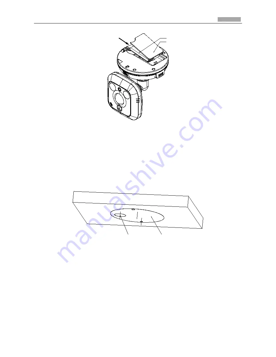
Figure 5-4
Insert Battery
3.
Stick the drilling template to the ceiling.
Notes:
For cement ceiling mounting, you need to use expansion screw to fix the camera, and the
hole of the expansion pipe should align with the mounting hole of the drilling template.
For wooden ceiling mounting, you can just use the self-tapping screw to fix the camera.
The ceiling must be strong enough to withstand more than 3 times the weight of the
camera.
Figure 5-5
Drill Template
Battery
Battery cover
Cable outlet
Drilling template